Continue to Site

Eng-Tips is the largest engineering community on the Internet

Intelligent Work Forums for Engineering Professionals

  • Congratulations KootK on being selected by the Eng-Tips community for having the most helpful posts in the forums last week. Way to Go!

Wide flange beam simply supported on blocking without top flange bracing

Status
Not open for further replies.

RBstructural

Structural
Aug 18, 2021
3
I work for a steel erector and I frequently see wide flange beams in the shop or yard sitting simply supported on timber blocking with no top flange bracing. I am wondering if there is a way to quantify the bending strength in this condition. In many cases, falsework designs or initially erected conditions are similar and I feel inclined to provide tie downs or temporary bracing to the top flange at supports where I am not sure how to determine the capacity if I feel it does not meet AISC Appendix 6 and AISC F1(2) requirements for restraining points of support against rotation about their longitudinal axis. Having a way to quantify the strength in a beam where it is supported on blocking at its bottom flange with nothing restraining its top flange could be very advantageous. I'm wondering if anyone can provide a reference or shed some light on this scenario.
 
Replies continue below

Recommended for you

There are equations in numerous design specs and publications to calculate lateral torsional buckling (LTB). Of course, a beam that may buckle under it's own self weight sitting in the yard, would be odd case, I would think, as it would be too slender to be of much use as a load-carrying member.

Rod Smith, P.E., The artist formerly known as HotRod10
 
A "Compact Section"

"When you have a compact section there is no possibility of local flange or web bucking to prevent attainment of the full sections yield strength. In common terms, the beam will not have a local failure (i.e. your web buckles) before the beam has global failure."

 
But even a compact section needs to be torsionally braced at each end to prevent lateral torsional buckling, does it not?

BA
 
Good practice would dictate some form of torsional resistance at each support. Fastening the bottom flange to the support provides some torsional resistance. Perhaps that could be assessed, but to load a beam completely unattached to the supports is a non-starter in my opinion.

BA
 
RBS -- I've used the BS5850 rule (add 2d to the LTB length) mentioned in steve's thread before in this circumstance. Perhaps not a robust solution for incredibly slender sections, but for the typical beams used in cribbing and falsework situations it works well.

If it is a slender section, also be sure to check the rigid body stability with some incidental lateral load applied at the top flange.

----
just call me Lo.
 
I believe a torsional load and resulting "overturning instability" needs to be addressed separately from the lateral buckling and local web buckling phenomenon.

 
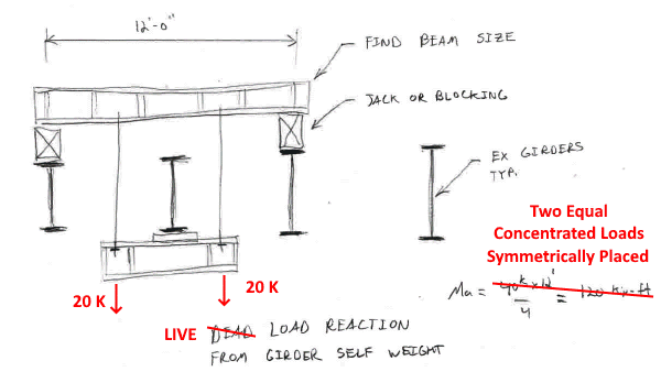
Thanks for the replies. Adding 2D seems like a practical method. I am not very familiar with non-american codes. Attached is an example of a temporary support scenario that I've run across for bearing replacement of bridge girders with the bridge deck removed. Adjacent girders are used to support the girder where the bearing is being replaced. I get close to 11 percent difference in bending strength of the support beam using the 2D method compared to somehow bracing the section at the blocking. That does not seem like that big of a reduction. I'm curious how others would approach this scenario. The other reference I've come across is stability of metal structures but I don't have access to it.
 
 https://files.engineering.com/getfile.aspx?folder=da610429-e3f0-4f35-9b1e-f9a294faf9ad&file=Sample_Falsework.pdf
RB, that looks comfortable to me because you've got bottom flange loading and stiffeners at/near all the load points.
 
RBstructural said:
Attached is an example of a temporary support scenario that I've run across for bearing replacement of bridge girders with the bridge deck removed.

I'm curious how others would approach this scenario.

Since the example is typically part of a Contractor's "ways & means", I'll give the approach I would use as a former Bridge Contractor (and PE at that time).

1) A Bridge Contractor will have an inventory of random steel shapes (not necessarily just W shapes) from previous projects. Perform the calcs (backwards) to see if an available shape can be successfully used as the temporary beam. By "backwards", I mean use the structural properties of the shape to see if it is suitable, not that it is efficient or ideal.

2) The moment calculation shown (point load at center of temporary beam) is "wrong". I know that is conservative, but you have absolutely no idea how conservative. Perform the moment calculations "accurately" (two equal concentrated loads symmetrically placed). Then make an informed engineering judgement decision on how conservative you should be.

3) As far as the temporary beam is concerned, weight (40 kips) of the supported girder is live load, not dead load... treat it as such in the calcs.

4) For this application, reasonable temporary beam deflection (high moment of inertia) is not really important. What is important is low bending stress (high section modulus). Also, minimum weigh of the temporary beam is not important if a higher weight beam means fabrication labor (e.g. installing beam stiffeners) can be avoided. For stability, a temporary beam should have a "low" center of gravity and a "wide" flange.

5) A temporary beam needs to be "robust" to take handling and unexpected loading that may occur.

6) Considering all of the above factors, I would not intentionally select a "tall / skinny / thin web" beam, but a "short / chunky / thick web / wide flange" beam... in this case say a W14 or maybe even a W12 instead of a low-weight W16.

Temporary_Support-600_u7k0s3.png


Contractors look at problems like this in a different light than Design Engineers.

[idea]
 
BridgeSmith, can't long span bridge girders buckle under lifting?

Possibly if you tried to pick a girder piece that was going to be composite at the ends, it could be subject to LTB, since the concrete deck essentially becomes the top flange. I didn't see anything in the OP that indicated this was the case.

Rod Smith, P.E., The artist formerly known as HotRod10
 

SlideRuleEra said:
2) The moment calculation shown (point load at center of temporary beam) is "wrong". I know that is conservative, but you have absolutely no idea how conservative. Perform the moment calculations "accurately" (two equal concentrated loads symmetrically placed). Then make an informed engineering judgement decision on how conservative you should be.

3) As far as the temporary beam is concerned, weight (40 kips) of the supported girder is live load, not dead load... treat it as such in the calcs.

4) For this application, reasonable temporary beam deflection (high moment of inertia) is not really important. What is important is low bending stress (high section modulus). Also, minimum weigh of the temporary beam is not important if a higher weight beam means fabrication labor (e.g. installing beam stiffeners) can be avoided. For stability, a temporary beam should have a "low" center of gravity and a "wide" flange.

5) A temporary beam needs to be "robust" to take handling and unexpected loading that may occur.

I agree with SlideRuleEra, with the following comments:

2) It is equally wrong to add 2D to the span. Again, it's conservative but you have no idea how conservative it is. Much better to calculate the moment as it is, 20*a where a is the distance from support to hanger, then select safety factor to suit. OSHA would expect a safety factor of 5 for this application.

5) A robust beam is good, but if it's not nailed down, the unexpected loading on a construction site could cause unexpected problems. The beam should be nailed down to the timbers at each end and the top flange should be braced. A couple of strap ties engaging the top flange and nailed to the timber would seem reasonable.

Looking at the sketch, I think I would have some concerns about the stability of the supported beam which delivers a reaction of 40k. It must be well braced to adjacent beams before the full load is applied.

BA
 
BA, the 2D is only added to calculate the effective length for LTB resistance (ie reduce calculated capacity). The bending moment is calculated as you said, using actual span and load position.
 
Thanks steveh49, I misinterpreted that. One of the features of the arrangement shown here is that the load hangs down well below the bottom of the beam, making failure by LTB unlikely. I don't believe that a 2D addition to effective length would be adequate compensation if the load were placed on top of the beam. Without some form of torsional bracing at each end, the theoretical buckling length is infinite, or perhaps, undefined.

BA
 
I wouldn't do it for tall, skinny beams and I had thought that a wide flange beam was the type that has flange width equal to depth (called universal column sections here). But I see that a US Wide Flange beam can actually have narrow flanges despite the name.

Top flange loading would also be a worry to me. The British Standard effective length for dead bearing plus top flange load is equivalent to the Australian effective length for top flange loading but with torsional restraint at supports. However, the setup I mentioned in the other topic was tall, skinny, top flange loading and no torsional restraint at support, was visibly deflecting under the load, and evidently stable.

The only way I could justify using this for something major is if HD bolts would not be 'active', ie no tendency for one edge of the flange to lift off the support and friction adequate for lateral load, including a notional lateral load for robustness.
 
Status
Not open for further replies.

Part and Inventory Search

Sponsor