Continue to Site

Eng-Tips is the largest engineering community on the Internet

Intelligent Work Forums for Engineering Professionals

  • Congratulations KootK on being selected by the Eng-Tips community for having the most helpful posts in the forums last week. Way to Go!

Wind Loads on "Trussed Tower"

Status
Not open for further replies.

temporar

Mechanical
Oct 20, 2023
2
Hi, I'm new and fairly lost. I'm trying find wind loads using the ASCE7 trussed tower section on some open framed tooling platforms (similar to attached picture). I'm having trouble deciding how to calculate and apply these loads. I've also been referencing the ANSI/TIA-222 to help clarify some points.

I'm currently thinking I should:
1. consider the 0° and 90° wind directions, calculate solid area based on the projected shape of the entire structure in each direction
2. find the forces associated with those two directions
3. apply either of those forces at some angle (between -90° to 90° relative to the respective face) that provides the worst case for my members and reactions

But I'm unsure of a few things.
1. Should solid area be based on the members within the plane of a face of the tool, and not the all members projected onto that face? The first way seems to be what the ASCE7 is saying, but it feels wrong to ignore surfaces behind the face.
2. ASCE7 says "wind forces shall be applied in the direction resulting in the maximum member forces an reactions." This means I need to consider every angle from 0-360, correct?
3. Can I use the solidity ratio for wind directions normal to a face, and then apply the resulting force at an angle to the same face? Or do I need to be recalculating the solidity ratio (and force) for each angle?
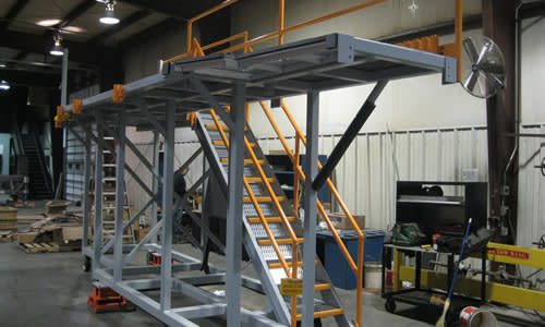
custom-metal-fabricated-mobile-work-platform-WB-Industries-gal_oiblfg.jpg
 
Replies continue below

Recommended for you

Welcome to Eng-Tips. And congratulations for having a good question as your first post. Plenty of first time posters have poor questions with insufficient information and disappear quickly. Regarding your question. I don't have too many thorough answers as I use a different code, but I'll follow along because some of your queries are good.

temporar said:
I'm currently thinking I should:
1. consider the 0° and 90° wind directions, calculate solid area based on the projected shape of the entire structure in each direction
When you have multiple frames in line that the projected shape of the entire is not an accurate representations of the area affected by wind load. However I can't speak to how your code treats such things.

temporar said:
2. find the forces associated with those two directions
3. apply either of those forces at some angle (between -90° to 90° relative to the respective face) that provides the worst case for my members and reactions
In general 2 directions will often be sufficient. But not always! I'd be curios on other peoples take on this and how they generally handle things. Though for square OR close to square shapes considering the 45° is important.

temporar said:
2. ASCE7 says "wind forces shall be applied in the direction resulting in the maximum member forces an reactions." This means I need to consider every angle from 0-360, correct?
Yes. However a few minutes thought should have the number of directions reduced to 4-8. The structure you show there will clearly have higher loads across it than along its length. But you'll want to check all 4 orthogonal directions to ensure that your lateral system is suitable for task.

EDIT: Some further information here:
 
Thanks for the kind words. I do try and ask good questions!

human909 said:
When you have multiple frames in line that the projected shape of the entire is not an accurate representations of the area affected by wind load. However I can't speak to how your code treats such things.
Are you saying that the single frame is a more accurate representation?
Am I misunderstanding "shielding?" The ANSI/TIA reference has a picture showing there's "no shielding" beyond 4 diameters of a member, and I took that to mean every surface further away from each other than 4 diameters should be considered. (I guess that would mean the projection is actually underestimating the total surfaces...)

human909 said:
Yes. However a few minutes thought should have the number of directions reduced to 4-8. The structure you show there will clearly have higher loads across it than along its length. But you'll want to check all 4 orthogonal directions to ensure that your lateral system is suitable for task.
Thanks for the confirmation. The word "consider" was definitely doing a lot of work in that sentence.

If anyone has more input on this I'd appreciate your thoughts.


If these are going to be outside, you need to include your icing loads, and wind on ice loads. This could increase your overall square footage of your profile quite a bit. Ice loads are covered in ASCE 7, chapter 10.
 
Status
Not open for further replies.

Part and Inventory Search

Sponsor