Continue to Site

Eng-Tips is the largest engineering community on the Internet

Intelligent Work Forums for Engineering Professionals

  • Congratulations SSS148 on being selected by the Eng-Tips community for having the most helpful posts in the forums last week. Way to Go!

Window Attachment to CFMF 1

Status
Not open for further replies.

sticksandtriangles

Structural
Apr 7, 2015
494
Hello,

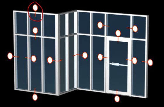
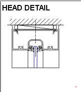
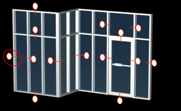
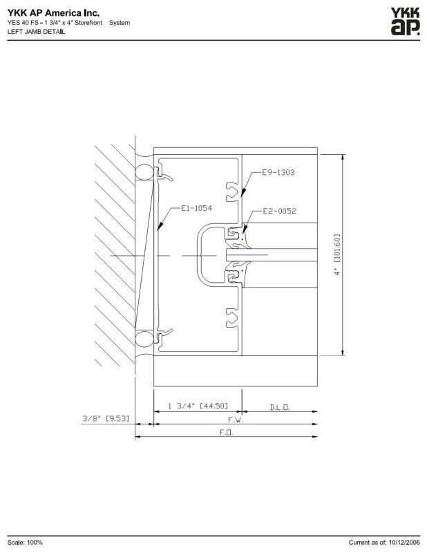
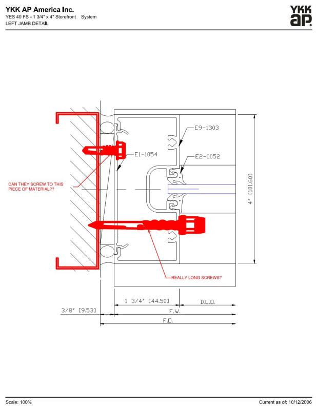
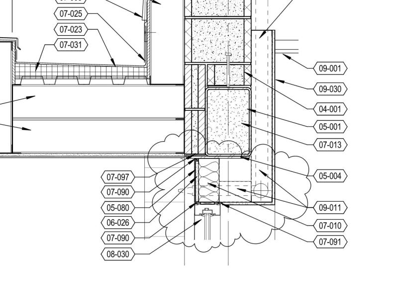
I have been designing a good amount of CFS lately and the intersection of windows to CFS framing has been a mystery to me that I often ignore. I see cryptic architectural details show thing like this:
kROGE_vf8cvc.jpg

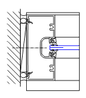
I would like to see window shop drawings to see how they make this attachment but I have never once got a hold of these. (Should I be asking for them?) I have been assuming that the window guys are making attachments at somewhat fairly regular intervals that allows me to distribute load as a uniform load to my CFS framing. I would like to be to confirm that this assumption is correct for most applications.

I guess that this also brings up the question as to if the window spans vertically or horizontally. I have seen discussion on here that people assume both and design jambs for one condition and sills and headers for the other condition.

Does anyone have a good reference document on this connection or can they speak from experience?

Thanks for the opinions in advance.

S&T
 
Replies continue below

Recommended for you

As you might expect, different anchorage details for different systems. Your assumption of attachments at regular intervals is reasonable for storefront systems; maybe not so much for curtain wall systems.

For a vertically-spanning storefront system they often use screw-spline fastening. Glazing spans horizontally, and is supported by the vertical mullions. These verts are in turn secured to the abutting horizontal (head/sill) mullions via screw fastening into the spline extrusions of the latter. Then the horizontals are thru-fastened to the structure via material-specific anchors installed local to the horizontal/vertical mull intersection. Uniformly spaced anchors are used along the "span" of the horizontals as well.

Other anchorages include shear blocks or T- and F- anchors, the latter being used for more heavily loaded curtain wall systems. For the deeper systems (mullions 6"+) you can imagine that the localized reactions at the ends of the mulls are a bit more significant and might require some attention if the direct substrate is going to be CFS.

I would encourage you to go to some of the glazing manufacturers' websites and take a look at the details they have available for the plethora of systems they offer. YKK AP has some nice online manuals with exploded/axon views of the systems and how they go together.

 
I just worked on one where there was no minimum gage specified for the job. I provided a minimum of 18ga members around the windows. The storefront supplier is asking for a bunch of extra money from my metal stud client as he wants 16ga minimum to minimize the amount of connections he requires. Believe it or not, the GC is siding with him!
I agree, it seems like a mystery on every job. I generally provide 14ga members min. if tall, vertically spanning storefront is used.
 
Thanks Seppe,

It seems like you are speaking a different language with all the terms you are throwing out there!

Few questions, and again I apologize if I get my terms wrong here.

So I am dealing with a storefront window condition and I went to YKK AP and the connection details are not shown on the few storefront systems that I was looking at. The storefront module YES 40 horizontally spanning mullion shows no attachment into the above supporting system (header CFS).
Capture_doa3hf.png

Capture_bseezk.png


The vertical "jamb" mullion detail also shows no screw attachment into the side support (jamb CFS).
Capture_wtvfe7.png

Capture_dgv9g6.png


I guess my question is are they drilling through all the way through the aluminum extrusion they provide?
This is what they show,
yes40fs_d4_wokb90.jpg

This is what I imagine,
yes40fs_d4_wcrrxm.jpg


Let me know what is more plausible of the two screw positions I show or if I am out in left field.

Thanks
 
Now that I am looking at these pictures a little more, I am guessing that the flat plate type structure (E1-1054) would be attached first with screws as I show in top screw of my last image. Then they slide the E9-1303 structure over? Is E9-1303 attached to E1-1054 in anyway? It almost looks like you have to push it over the tabs of E1-1054 and that is a good enough connection?

This makes me want to do some site visits as it clear I have no idea how these things are assembled!!!
 
E9-1303 could be secured to the structure by anchorage through the pocket, right where they show the centerline.

The long screw you show would be a no-go because it would actually be exposed where you have it positioned.

The E1-1054 snap-in closure piece could be directly fastened, but I wouldn't exactly consider it a reliable load path to get the load from the mull (E9-1303) back to the substrate - certainly nothing the manufacturer would quantify for you, anyway.

Some decent details (showing various attachments) in the link below. Shows the screw-spline relationship, and even a shear block connection as well.

 
Status
Not open for further replies.

Part and Inventory Search

Sponsor