rajubhai26
Student
- Dec 8, 2024
- 8
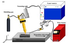
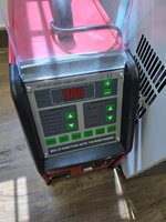
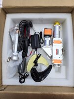
Hello everyone. I would like some guidance on my experimental setup for my Final year project. I am required to make an experimental setup for my WLAM. I need help on the some equipment's that needs to be bought such as XZ axis moving stage/platform required to conduct layering experiment. I have referred many journals but mostly uses 6- axis robotic arm for movement. The project is under tight budget. For the time being, I have the coolant, wire feeder, Laser welding head, laser power system, and laser controller. Below are some other requirements for the project. Please from your experiences please give me some suggestions on how to pursue this. Max power rated for laser welding head 2kW
For the laser head, we may fixed it vertically but may include a manual/motor adjustable Z-axis movement. We are required to find working distance from laser head to focal point (References to Collimation and Focal lens). We will place the Wire feeder accordingly at appropriate angle 30/40/45 degs.
For wire feeder, Need to consider type of wire feeder, diameter, feeding rate. Our max input for welding head is 2000W. Required shielding gas with controlled flow rate. 99% Argon gas.
Cooling Equipment setup Optical Fibre laser bending radius ( If not mistaken, 100mm)- may need to know how and where to bend
Laser settings ( Laser power, type of laser: Pulse/continuous)There were calculation from journal for wire feed rate and some others from journals for consideration
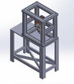
For main structure, We can use the aluminium column seen last time to build in box shape connected with brackets.
Lastly, we must integrate shielding gas, Wire feeder, Laser power (On/OFF), Water Coolant with PLC or some form of controller to initiate these in sequences


