Eng-Tips is the largest engineering community on the Internet

Intelligent Work Forums for Engineering Professionals

  • Congratulations waross on being selected by the Eng-Tips community for having the most helpful posts in the forums last week. Way to Go!

Wire rope tension

Status
Not open for further replies.

Buddha01

Structural
Sep 26, 2022
3
GB
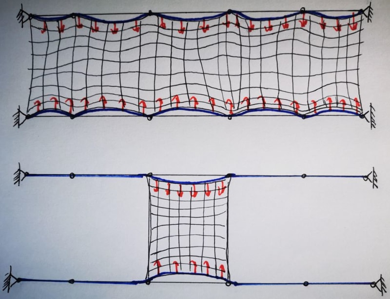
Hi all - Developing concepts for a walk on tension access platform. When the walk on net is held taught to limit sagging (both SW and service loads) it produces a lateral load each side and in my case the net is restrained along two parallel sides. The net hooks on to parallel straining wires that are pre-tensioned wire ropes. The below sketch illustrates the concept - blue are the wire ropes (deflections exaggerated) and the red UDL's represent the net lateral pull and for this purpose can be considered equal full length in both diagrams. The intermediate supports allow the ropes to slide and rotate freely so they 'guide' and only provide vertical and lateral restraint when rope equilibrium is found. I am wanting to minimize the quantity of intermediate fixings (increase crs) but this is having a significant increase in the rope tension and size required in order to control deflections. Fundamentally I had wanted to ask whether it is correct to assume the tension in the rope is a multiple of the tension developed for a single bay when determined in isolation? So for the two diagrams given the upper diagram rope tensions would be 5 times the tension in the ropes in the lower diagram; again all net loads are equal in both diagrams. Assuming this is the correct approach I may have to consider to split the system into smaller rope lengths and to introduce additional anchoring supports. Thanks for any feedback.
Rope_net_sgxbul.jpg
 
Replies continue below

Recommended for you

Buddha01 said:
The intermediate supports allow the ropes to slide and rotate freely so they 'guide' and only provide vertical and lateral restraint when rope equilibrium is found.
Why would you want this? This would greatly increase deflection when only one 'bay' is loaded.

It also makes introduces significant other challenges to your problem.

Buddha01 said:
Fundamentally I had wanted to ask whether it is correct to assume the tension in the rope is a multiple of the tension developed for a single bay when determined in isolation? So for the two diagrams given the upper diagram rope tensions would be 5 times the tension in the ropes in the lower diagram;
No it is not. You have a highly non linear system there with interacting catenary systems.
**(I haven't actually calculated it, my brain is a little tired, but I highly doubt linear behaviour drops out neatly out of this complicated interaction. Afterall tension based systems tend toward infinite force as the deflection lessens. Deflection of an individual bay reduces as more load is added to other bays.)
 
Yes, 100% agree it is a non-linear system. I am simply running hand calcs for an assumed limiting deflection for the net and wire rope when uniformly loaded in order to arrive at a starting point for fixing crs and rope diameter. I am putting it out that if the net load on the rope is uniform across 'n' bays then the tension increases also by roughly a factor of 'n' bays. Appreciate the rope modulus changes with tension etc. but as a general principle the rope will have a low utilization (~FoS of 5) so fairly safe to adopt a trial E' in the low 100's (GPa). Also considering that -ve temperature adds tension to the rope to ensure service conditions are met. I may have to introduce straining posts more frequently yes.
 
Buddha01 said:
I am putting it out that if the net load on the rope is uniform across 'n' bays then the tension increases also by roughly a factor of 'n' bays.
And I am putting it out there that this is not the case as all or at the very least depend strongly on the scenario. Because it is non linear.

With a system with an extreme amount of slack then you could readily have the scenario where the tension in wire is identical whether there is 1 bay loaded or 2 bays loaded or even 5 bays loaded. AKA ~T=1kN for n=2 or n=100. Whereas with ZERO slack you can also end up in a situation where T=1kN for 1 bay and T=1 for n=2 or n=100 bays EDOT where T is linear with bays..

So far with those two extreme examples we have the tension being invariate with the number of bays loaded!

However I can also pick a middle case where T rises significantly as n increases... But at this point I am giving up without resorting to calculations. Either way, I have shown that the relationship is non linear and non monotonic with regard to the amount of slack in the wire. We have also shown that T(tension) can be invariate with the number of bays.

Both are strong arguments against making your linear assumption. Though this does not rule out that in some configurations that linear assumption could be approximately correct. I can roughly imagine a situation where it does seem to approach a linear behaviour. But I'd want to pull out my pen and paper to check and be sure.

It is a complex system. Make some suitable assumptions for your loads, your slack and the stiffness of the wire and do the hand calcs.

EDIT: Some heavy edits on my behalf as I made mistakes. With the edits I might have even made the case for your linear assumption being suitable and conservative (oops!). But I need to attend to something else now. I hope you can interpret what is written including the edits.)
 
Status
Not open for further replies.

Part and Inventory Search

Sponsor

Back
Top