Continue to Site

Eng-Tips is the largest engineering community on the Internet

Intelligent Work Forums for Engineering Professionals

  • Congratulations KootK on being selected by the Eng-Tips community for having the most helpful posts in the forums last week. Way to Go!

Wood cracking in a recent structure

Status
Not open for further replies.

Jeepitou

Structural
Feb 4, 2016
12
Hello everyone,

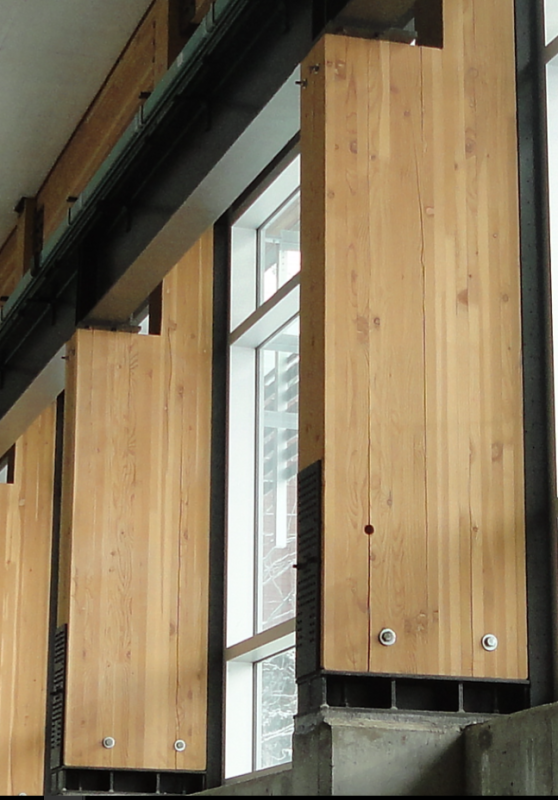
I recently did an inspection of a glued laminated wood structure which had a lot of cracking in the columns. The beams seemed to have little to no crack.

I think it's principally due to shrinkage of the wood, since I could unscrew bolt from the wood by hand. The problem is that some crack are really deep, they are through the whole thickness of the column.

I have some difficulty thinking that only the drying of the wood could do such damage to it, unless they put it in a pool just before installation.

Any of you seen anything similar? Or have any others causes in mind that could have such behavior?

Thanks :)
 
Replies continue below

Recommended for you

Are there random cracks or maybe between the lamina? What are dimensions of the column? Shrinkage (poor moisture control) can cause this.

If you think it's critical, reinforce column with fully threaded screws.

Structural timber engineering
 
The cracks are principally between the lamina. But there is some important crack in the perpendicular direction of the lamina. The columns are ±300x600.

 
Have you notified the glu-lam supplier of the issues for their input?
 
If this is milimeters, then columns are huge (in width in particular). With mass timber like this, cracking is an issue and maybe the supplier just didn't take enough care.

Does it look like delamination ?
 
Yeah it is millimeter, pretty huge column indeed. They are holding a overhead bridge crane. I don't think it is delamination since the cracks aren't in straight line.
 
1. Immediately tell the owner, the bridge crane operator, and your boss! It is in the load path of a crane, and you're liable until completely analyzed structurally and either replaced or reinforced properly.

It's a load path, people and loads are affected already as it settles and twists. Now, true, it may not fail.
 
Agree with boo1 that we need some pictures in order to give advice. In the meantime, start raising hell. Cracked glulam columns carrying an overhead crane system raises all sorts of red flags.
 
Jeepitou:
Just a couple thoughts...., Surprisingly enough, many times cracking which it parallel to the grain in a column does not drastically change the cap’y. of the column much. But, I would still really get after the GluLam supplier to explain this and make it right. Each column should be inspected for how critical the cracking really is, and for a repair or replacement determination. Secondly, with 24" wide columns, the crane rail beams must be mighty large too. Is it possible that when you have max. beam deflection, you are applying all the beam reaction to only one or two plys of the column, and you are getting some very high horiz. shear type stresses btwn. those two outer plys and the rest of the plys, as the reaction tries to transfer into more of the column cross section? Some photos, plans, details, loads, calcs., design info. sure would be helpful in our getting the picture of what you’re looking at.
 
Hey guys,

Thanks for your opinion on the subject. I've joined a picture of the glulam columns. You also can see the beam that support the hang the bridge crane on top of the column.

GLULAM_zfe439.png
 
Here is another crack in the perpendicular direction

GLULAM_1_loypcx.png
 
Is this a moment connection at the base? Looks like the bolts and front steel plate prevent movement and with change in moisture it cracked.
Top and bottom of the column I see some kind of reinforcement. Is this full depth?
 
Second picture: is this steel bracing? Is it connected full depth into the column with bolts or screws (how long)? With large forces in the brace this might tear column apart.

Cracks reduce bending resistance but in compression only this might be ok.
 
I don't know if it is a moment connection, unfortunately don't have the plans. They drilled a hole to see the depth (on first photo) and it was.
 
They'd have to extend that thin front plate all the way up, through-bolt the whole assembly from extended front plate to (another) back plate, then side-clamp both sides with (two more) face plates on both sides.

Kind of like a concrete form or "water tank" enclosure: The 4x side plates would be needed to hold the wood from continuing to expand under the compression load. The wood by itself has no tension (moment) capability now, and is squeezing itself apart under the compression load. SO the through-bolts are essential because a screw or lag bolt has no strength left in the wood to "pull against" and the screw's own threads will be driving it further apart.
 
Personally, I do not like the connection, particularly the notching of the column to receive the steel beam. This should have been done with two separate members, stitch bolted together if necessary.

I think that inherent to the problem is a difference in vertical bearing stresses, that from the steel beam load, and that from the floor/roof system above as it appears that the columns may extend up to support some of the structure above, floor or roof. If the difference were too great, it could induce vertical cracking.

Mike McCann, PE, SE (WA)


Agree with others that it is most likely restraint shrinkage cracking. An unfortunate, dare I say silly, selection of material for support of a crane runway. Why not steel?
 
Looks like drying shrinkage cracking to me! Especially at the bottom, the outer lams are restrained by the face plates and all those screws.
Might be able to reinforce the column with "interior shear reinforcing" such as full length threaded screws.
Please follow up with what you find.
 
Status
Not open for further replies.

Part and Inventory Search

Sponsor