Continue to Site

Eng-Tips is the largest engineering community on the Internet

Intelligent Work Forums for Engineering Professionals

  • Congratulations cowski on being selected by the Eng-Tips community for having the most helpful posts in the forums last week. Way to Go!

Wood Diaphragm Question 1

Status
Not open for further replies.

zrck99

Structural
Dec 19, 2014
82
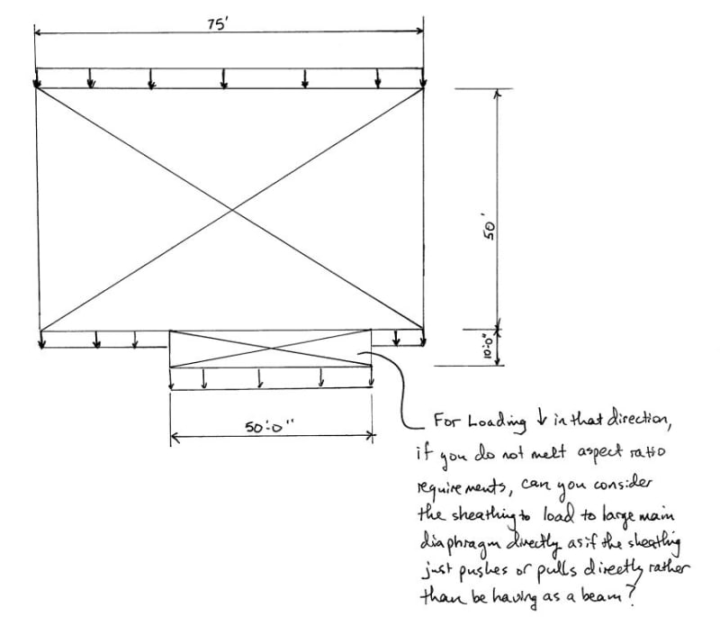
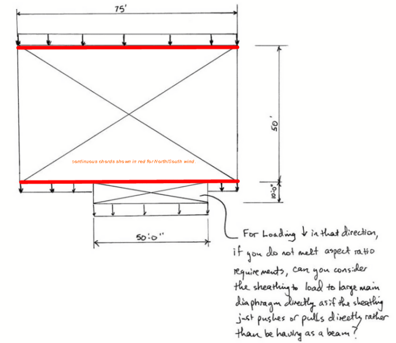
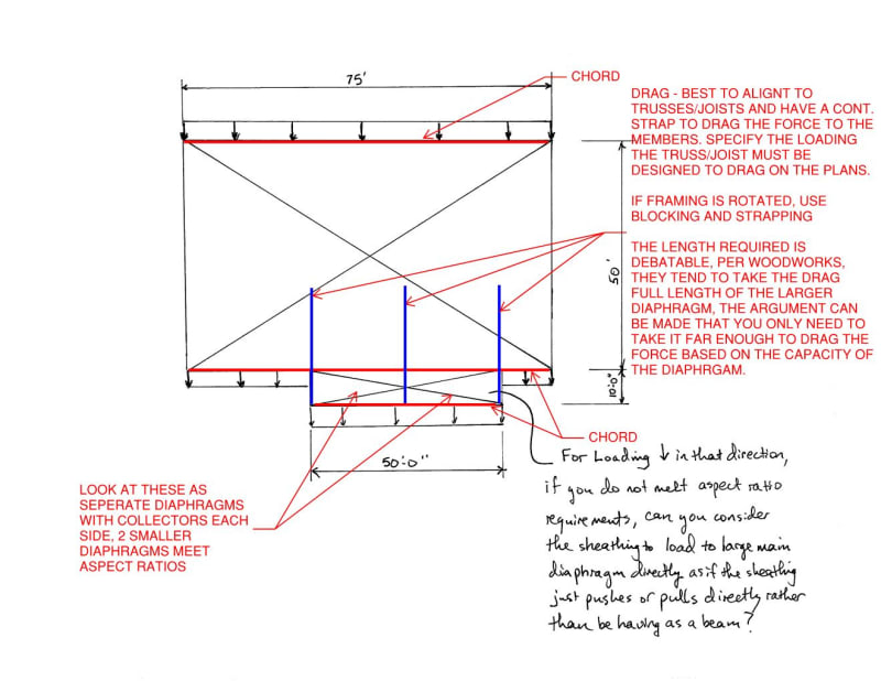
The attached sketch shows a large 50' x 75' wood diaphragm with a small bumpout 10' x 50' diaphragm next to it. What are the rules for treating a small side portion like the 10' x 50' bumpout as if it will not act as a beam but rather just transfer its shear directly back to the main diaphragm?

Thanks.
 
 https://files.engineering.com/getfile.aspx?folder=e73a3103-ebc7-4f67-a27a-867fe980cbc0&file=DIAPHRAGM_QUESTION.pdf
Replies continue below

Recommended for you

OP sketch repeated below.

I believe that the only rule is that you have to positively attach the baby diaphragm to the poppa diaphragm such that the tension/compression load transfer mechanism is plausible. If it's a pitched roof with the valley done in over framing, that can actually be kinda tough to do by the book.

c01_bxd2lv.jpg
 
It boils down to the load path. How are the two joined? Will the sheathing lap or is there a joint of some kind? You could do discreet collectors that transfer the shear back to main diaphragm if it isn't continuous sheathing.
 
The chords shown in red below must be continuous for the diaphragm to work.

Diaphragm_faewvm.png


BA
 
See below for an example of how to deal with aspect ratios for this:

DIAPHRAGM_QUESTION_yueu58.jpg
 
Aesur,

I've gone through the textbook "Analysis of Irregular Shaped Structures" that the woodworks paper is based off. It has a lot of great examples but I haven't found this question addressed in the book. I agree that what you've shown is one proper way of handling the loads but I'm just wondering if treating the sheathing as a tension/compression tie is incorrect for some reason.

My understanding is that the reason to be concerned about aspect ratios is because your end goal is to get your load from the interior of the diaphragm out to your shearwalls. If you do not meet aspect ratios, then you won't be able to collect your load at your shearwalls effectively. In my case described here, I'm not trying to focus my load at the blue collectors. Really, I would rather not collect the loads and just transfer them directly back as a uniform load to the main diaphragm. So the question really is, do any codes or papers/textbooks address treating the sheathing as a tie for direct force transfer. I know that you aren't allowed to use the sheathing as a tie to transfer focused chord forces/collector forces but I haven't found anything addressing this case.

As a side question, you mentioned that when using collectors like the ones shown in blue, they tend to run the collector back full width across the diaphragm in order to use the main diaphragm's back chord as their transfer diaphragm chord. Then you say that the argument can be made that you only need to take it far enough to drag the force based on the capacity of the diaphragm. What is the justification for that argument? As long as the sheathing can take the load out of the collector and the main diaphragm can handle the point load from the collector without having too much shear at that section then you don't need to extend full width?

Thanks.
 
zrck99 - another reason for the aspect ratios is testing. As the aspect ratio grows, the empirical results begin to vary unacceptably from the published equations or there simply isn't enough empirical data to compare to the equations.

I think what you suggest is possible, but you have to cautious about the sheathing layout. Given the relative sizes, I wouldn't be too concerned about the central blue collector so long as the sheathing is properly staggered - which will require additional detailing. Load in the other direction, however, would likely necessitate the outer blue collectors (depending on shear wall layout in that direction).
 
I may have lots more to say on this but, before I get into it, is it safe to assume that we're talking about two intersecting gable roofs here as in your other thread? Or are we discussing flat roofs now?

It is common to not run the collectors the entire width of the diaphragm and I agree that it's reasonable. That said, from a theoretical perspective it does cause some problems. It goes largely unstated but an implicit assumption of our diaphragm designs in wood is that the sheathing acts as what is known as a pure shear diaphragm. That, meaning that we assume that the sheathing transfers in plane shear but not in plane tension or compression. The detailing of sheathing fastening makes the transmission of in plane axial force dubious.

With the partial depth collectors, you're setting up a scenario in which the sheathing does have to transmit in plane axial forces and, consequently, the shear panel assumption is violated. The textbook way to deal with this is to have not just partial depth collectors but true sub-diaphragms complete with their own boundary members. Of course, for stick frame wood buildings in most parts of the world, this is viewed as being impractical.
 
Kootk,

Yes, the same building as before is the source of the question so it is two gabled roofs intersecting, but ultimately the same thing applies in lots of wood framing scenarios. Like an apartment building floor where the outer walls bump in and out. You can block and strap across the jogs in the wall to create a continuous inner chord but then you still have the small bumpouts to deal with. Tying each side of the bumpout back into the building is a lot of extra detail work in the field if it is acceptable to just treat the floor sheathing as a tie back into the main diaphragm.

With your second point about tying the transfer diaphragm truss all the way across the building, I've gone through The Analysis of Irregular Shaped Structures by Malone and Rice so I can see the logic in going all the way across in order to properly engage the rear chord of the transfer diaphragm but as you've also pointed out, doing sort of detailing for wood framed buildings seems overblown. If you can get the load into the sheathing by blocking and strapping out say 3 truss spaces, It seems insane to block and strap all the way across the building.
 
I withdraw my statements now that we know this is a gabled roof. There are other factors to consider now.

Is the intersecting roof built over the primary, or is the primary interrupted to make one large attic/living space? In either case, the diaphragms won't quite interact in the same way you've depicted (though the overbuilt case will be somewhat similar).

 
Pitched roofs are the goddamn bane of rigorous diaphragm design. Frankly, for this situation, I can think of no legit strategy guaranteed to not raise the hackles of your contractor.

Another factor is that, in my opinion, this is intimately related to another common problem we have with this system: short of balloon framed gable walls, it's always a problem bracing the joint where the bottom of the gable end truss meets the wall top plates. For that reason, I think it best to do the ride along connection work at the ceiling level as it takes care of both issues nicely (sketch below). Some other, nutty possibilities:

1) Turn your valley set the wrong way, run your bump out blocking high and in line with the valley pieces, and fasten the valley pieces to the trusses below. Yuck.

2) Split your bump out trusses with a ridge girder down the middle running NS, strap that to a main building truss, and halve your diaphragm aspect ratio. Double yuck.

3) Call your bump out diaphragm the bump out plus the sheathing over the valley sets and then say that you don't have an aspect ratio problem after all. This is surely the most practical solution but, then, you've gotta tell some weird story about having some kind of distributed member chord system under the valley sheathing etc.

c01_dnww31.jpg
 
In my sketch, note that you'd still need some messy, cross truss internal bracing to drag the roof deck level lateral loads down to the ceiling.
 
KootK - I know the ceiling makes for an easier analysis, but is it a good idea? You'd be relying on a gyp board diaphragm, wouldn't you? I've never liked GWB shear walls - they're allowed here (no earthquakes to speak of), but all it takes is a tree branch to poke a hole in the roof in the first hour or two of a hurricane and you're hosed. Seems like a similar situation here or am I missing something in your intent (like using the truss bottom chord as a compression member while the roof diaphragm controls the deflection of the system)?

 
phamENG said:
KootK - I know the ceiling makes for an easier analysis, but is it a good idea?

I'm not actually using the ceiling as a diaphragm so much. I spaced the struts as I did assuming that the wall top plates of the bump out could span between them. ~6'. Obviously, that's subject the number crunching of somebody getting paid to do the work.
 
phamENG said:
...but is it a good idea?

Got a better one? Seriously, I'm all ears. This is almost an untraceable nut without getting fancy somehow.

Another option is to omit the valley set and build the trusses up to meet the roof profile there. That's peachy structurally but ridiculous in terms of truss fabrication economy.
 
Got it. Thanks. In that case, the truss bottom chord will be in compression under horizontal wind loading. As one who has experience in the wood truss industry, is this a significant effect to be communicated to the truss designer or can it (usually) be handled by the EOR with supplemental blocking to reduce the unbraced length?
 
I was referring to using the ceiling as a diaphragm. I think using the entire truss system as a unit is a great idea, and that's essentially what you're doing. Everything above the top plate is designed as a unit to move more or less as one, so the whole system will deliver diaphragm-like restraint to the walls below.
 
1) The truss bottom chords will typically be experiencing meaningful tension when the strut compression loads are applied. As such, I'd expect it to often be the case that the compression introduced wouldn't even overcome that tension.

2) One could just as easily assume the strut compression to go into the top chords rather than the bottom. In fact, that's probably a more natural path given that the loads are ultimately assumed to be resolved by the roof sheathing. Of course, since it's a truss, the axial can and would go all over so who really knows.

3) I personally wouldn't bother communicating any special requirements to the truss guys for something on the scale of a house. If it's a huge industrial or commercial thing with little redundancy, that might get me motivated to do something like that.

phamENG said:
As one who has experience in the wood truss industry...

In all honesty, I didn't even know that there was such a thing as lateral loads back when I was designing these things myself. I was still in university to be an elementary school teacher back then.

 
Makes sense. I especially like point #2 as it can be applied to stick built gables, too. Thanks.

KootK said:
In all honesty, I didn't even know that there was such a thing as lateral loads back when I was designing these things myself. I was still in university to be an elementary school teacher back then.

That doesn't instill the greatest confidence in the industry. Though it feels like there's a story in the last part...
 
Status
Not open for further replies.

Part and Inventory Search

Sponsor