Continue to Site

Eng-Tips is the largest engineering community on the Internet

Intelligent Work Forums for Engineering Professionals

  • Congratulations GregLocock on being selected by the Eng-Tips community for having the most helpful posts in the forums last week. Way to Go!

Wood Floor Truss Contact

TRAK.Structural

Structural
Dec 27, 2023
141
Anyone on the forum here know of a person who would be a good technical resource for dealing with any number of issues that come up with wooden floor trusses? Seems like lately I get more calls about these things and they can turn into research projects real quick if you don't have a lot of information about manufacturer/original design loads/metal plate specifics/etc. I've been reading through TPI 1 to educate myself but I don't have any first hand experience with the design of these systems.
 
Replies continue below

Recommended for you

1) Me, except that I don't have software access. Working on it...

2) @RontheRedneck. Does have software access.

3) @Zoobie777. Pretty sure does have software access.

4) Maybe the Structural Components Building Council (Formerly Wood Truss Council & formerly my employer).

I know some locals that will run trusses for me on occasion but I need to be cautious about how often I go to that particular well.
 
What is the issue, is this for repair, modifying existing truss, changing loading, something else? Some additional context may allow us to help a bit more. I know you are looking for general assistance here, but all you are going to get is general answers, unless you provide more specifics.
 
As KootK said, I'm in the truss business. But unless you're in central Illinois, I probably can't help. I only have software access at work, and the company doesn't do consulting for hire.

I'd suggest finding a local truss plant and talk to them. They may or may not help - No way to know without asking. But they're more likely to help if it's project they have a shot at getting.

If you just have general questions I'm happy to help as best as I can.
 
Floor trusses are pretty simple other than figuring out the plate capacity. I don't run into situations where I have to do that very often though. For most alterations, they are easy to model in a 2-D frame program. Normally, most repairs I end up with involve sheathing the faces with plywood.
 
Koot and Ron - I may write out some general questions to bat around in a side conversation

Choras - The most recent request I've gotten has been about some water damaged elements of a truss at the end bearing where it is supported by an exterior wall. I haven't yet laid eyes on this condition but I'm thinking through some ideas on how one may repair this. Portions of the bottom chord, end diagonal, and end vertical have been reported to be damaged.

One approach could be to sister the damaged pieces, but that would require somehow making connections at the truss work points between old and new members that are no longer in the same plane...

another option may be to remove the damaged elements, splice the chords where necessary, and maybe use sheathing at any work points where the metal plates were removed to get the new members in

Maybe one other alternative (as XR mentioned) could be to just sheath over the damaged areas, I'd have to think about how best to justify with numbers the tensile and compression capacity of the sheathing though since the sheathing here would be essentially replacing some of the truss members

Hoping to get some pictures soon.
 
I would be careful trying to repair water damage trusses, Koot and Ron may be able to get more into it that I can, but I think the combined effect of understanding the full extent of the damage, addressing the issue of compensating for the compression perp issue and 'sag' due to the moisture effects, and finally, dealing with stiffness differences, it may be hard to actually get a repair to perform as one might expect based upon calcing on paper.

Mitek has a series of generic repairs on their website. I have not really looked through them, nor do I know how effective they may be, but might be a resource for the future?

https://www.mitek-us.com/resources/engineering/floor-truss-repair-details/
 
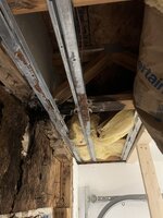
Got (1) picture taken from the site, see below. Obviously it doesn't show the full extent of damage but it is useful.

1736274092385.jpeg
Floor trusses are pretty simple other than figuring out the plate capacity. I don't run into situations where I have to do that very often though. For most alterations, they are easy to model in a 2-D frame program. Normally, most repairs I end up with involve sheathing the faces with plywood.
XR: 1. When you sheath the sides of a truss are you assuming that the sheathing takes all the load in the area and any nails to the chords/webs just hold it all together?
2. If the answer to the above is yes, I would think that maybe the numbers to check are stresses from tension/compression/shear in the sheathing and treating them as rectangular prismatic sections (basically a plywood beam instead of truss members with only axial load), sharing the load between the sheathing if done at each face of the truss?
3. If I am on track with 1 and 2 above, extension of the sheathing beyond the damaged area would be needed to develop the required forces, basically getting enough nails between sheathing and the truss members to transfer the loads through fastener shear?

Any other insight in to how this type of repair works or perhaps where my thinking is off track is appreciated.
 
@TRAX,

There is very little chord T/C at the end of the truss. Most of the load is going thru that last diagonal. I would think if you capture that with 6 ft ish long, 3/4" plywood on each face, you would be good.
 
You're still dealing with significant compression issues at bearing, and deflection of the existing truss due to failure at the existing nail plate. My suggestion would be to carefully jack the floor, replace the damaged web/chords with appropriately sized lumber, and find a way to field install nail plates. This all would likely need to be sized by a local truss supplier with a Mitek license, because you'll need to know required lumber grade and nail plate pattern.

Alternatively, is this a cantilever condition? Just size a sistered LVL with appropriate backspan to support the load, and bypass the truss.
 
I feel as though these trusses have been afflicted by something more than just water damage. There doesn't even seem to be any wood between the heel plates? Surely that's a condition that human being brought about somehow?

Or did the last diagonal kick the end vertical out the side of the building? I note that the plated connection at the top of that vertical doesn't look particularly distressed.
 
Dang - That is a mess.

No compression at all in the first TC segment, so that will help some.

As XR250 noted, most of the force is in the first diagonal. Looks like the plate at the first TC joint is intact?

You can double up that first diagonal web if it helps get enough nailing surface.
 
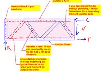
I see this a an outline of the method if you go the sheathing route. If you feel good about the condition of the diagonal nearest the bearing, you could shift the fastening one panel closer to the end to shorten up the repair.

c01.JPG
 
XR - Agreed on where the forces are towards the end of the truss, shear will be the biggest hurdle.

Koot - Great diagram. Would you retain the existing end block and place a new one on the outside of the sheathing at each side face of the truss??

Ron - Are you suggesting putting a new web member either above or below the first web and in the same plane so that it still fits between sheathing sandwiching the side faces? Nominal nailing of the new web to the existing just to hold in place and then more fasteners from the new web to the sheathing to do the work of transferring load?
 
Would you retain the existing end block and place a new one on the outside of the sheathing at each side face of the truss??

That's an option. It's hard to say without a better understanding of the original end condition and what state that stuff at the end is currently in. It would be tricky work but there may be some merit in doing away with the original end block and replacing it with a sturdy 4x4.

I can't tell if the last diagonal work point is over the bearing or beside it. If it's over the bearing, and a bearing check pans out, you might be able to forgo much attention to the end vertical other than to ensure that it can support any load coming in from above.
 

Part and Inventory Search

Sponsor