Continue to Site

Eng-Tips is the largest engineering community on the Internet

Intelligent Work Forums for Engineering Professionals

  • Congratulations SSS148 on being selected by the Eng-Tips community for having the most helpful posts in the forums last week. Way to Go!

Wood Framed Built Up Post Detail 1

Status
Not open for further replies.

zrck99

Structural
Dec 19, 2014
82
2012 AWC 15.3.3 gives the requirements for nailing together the separate plys of a built up wood post. I'm curious if other designers think it's necessary to state these requirements or provide a detail similar to Figure 15C in the design drawings. My firm's position is typically that by referring to it as a built up post we are referencing those requirements so unless the framer nails it appropriately, it is not a built up post. I'm not necessarily saying that line of thought is incorrect but was hoping to get some second opinions or examples of how other firms handle this.

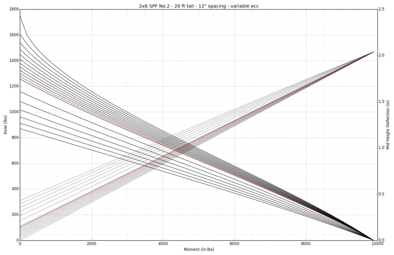
A second question, when designing built up wood posts, do you typically throw some eccentricity at the load just to make sure you're covered? For instance, if you have a girder truss supported by a (3) ply 2x6 built up post at an interior bearing location, depending on the loading and height of the post, if you put an inch of eccentricity on the post it can swing it from easily working to failing. It kind of leaves you in a quandary as the designer because if built appropriately, a wood post can easily work, but if as the designer you want to take into account the potential for the girder to not be centered over the post it looks like you need something like an HSS 4x4 tube. What are other designers thoughts here?

Thanks
 
Replies continue below

Recommended for you

Zrck99:
AWC, NDS, IBC, and the IRC have some std. verbiage and details on this detail, and your std. Structural Notes should say to design and build to those stds. and codes, so what else is needed. Except, of course, your std. built up posts should then be designed to those conditions. Then when you need something special you do design, detail and note to call out that special detail. I always add a note that special care should be taken in cutting the members to length so that they all are bearing, that is not std. stud cutting tolerances.

 
I'd be inclined to show the NDS detail in your drawings, especially if you do a lot of this kind of work. I think that it's asking a fair bit to have your builder go to the NDS herself to sort out what is required.

I've struggled with the eccentricity thing too. At a minimum, I do the h/6 thing which is recommended someplace I think. This is really a tiny amount of eccentricity but it at least allows me to identify crazy slender posts that will register as extremely sensitive to even this much eccentricity. If it's a situation where I'm more concerned, I may assume that the edge of the loading member aligns with the edge of the loaded member. We've had some discussions here where the consensus seems to be that slender posts loaded by deep beams may well adjust themselves in a way that would counter large eccentricities. Obviously, though, some serious designer judgment needs to go into that. You'll certainly not find it recommended in the NDS etc.


Thanks for the responses. I'd love to figure out more information on the h/6 thing if anyone can identify a source for it or previous thread where people discuss it.

 
d/6 produces a bending stress equivalent to the axial compressive stress.

P/A = M/S

A = bd
S = bd^2/6

P / bd = P e 6/ b d^2

e = d/6

edit: will dig thru my notes on this a bit more, did a deep dive a bit ago with KootK and some other folks on stud wall capacities.

edit2: here's one thread Link

Open Source Structural Applications:
 
So, I'm kind of new to EngTips.... Is there a way to respond to a specific person in the thread?

Anyways, Celt83, can you explain further? I get that if you have some unintended eccentricity in your loading that you will start to have bending stresses along with your axial stresses but why set them equal? Is that just an agreed upon rule of thumb?
 
Was just about to post a link to the same thread that celt did. I remember now. H/6 was just a recommendation in a software package I think.

 
Here is the impact to stud strength with various eccentricities, the red line is D/6 which is around 3500 lb axial capacity mark.
left to right lines are axial vs applied moment (applied moment is in addition to P*e)
right to left lines are mid height deflection (deflection is based on a uniform load where wl^2/8 would produce the applied moment and P*e point moment)

wall_e_test_sflsjb.jpg


list of e's checked, values are inches:
0.0
0.0916666666667
0.183333333333
0.275
0.366666666667
0.458333333333
0.55
0.641666666667
0.733333333333
0.825
0.916666666667
1
1.5
2
2.5
3
3.5
4

Short Stud:
wall_e_test_nv1ryi.jpg


Long Stud:
wall_e_test_pu10rp.jpg


Python file used to create the graphs in tandem with my wood_classes file: Link

Open Source Structural Applications:
 
I struggle with wood design codes in general not having provisions based on typical framing. On top of that, I feel that the NDS and IBC are really lacking in providing standardized details that are typically used on today’s wood framed designs. So many failure mechanisms are empirical in nature and cannot be easily calculated. My personal pet peeve is the interaction of uplift from hurricane ties on a sill plate and the anchor bolts that hold the sill plate down, which I have never been able to find a clear answer on.

One of the few that is explicitly stated is the built up column connection. I doubt there’s very many framers busting out 30d nails for 3-ply columns, they’re just gonna go to town on each layer with whatever is in their nail gun. And honestly I don’t really see why nailing each layer isn’t an option. That said, I like Simpson’s alternate of using self drilling screws, see link below:


In regards to the eccentricity, there’s no code requirement as others have pointed out. Manufacturers of engineered lumber use the d/6 in their column load tables, and Woodworks has recently added it as a default in their column sizing module, but I don’t know exactly what the origin of it is, I’m guessing it’s an approximation of the theoretical centroid of the beams bearing stress in relation to the centroid of the column. My take is that is probably warranted on an unbraced post. But if it’s a column that’s integral with a sheathed stud wall system and the beam is bearing over the full depth of the wall, there’s so much redundancy involved that it seems excessive to factor in the eccentricity since is has so much influence on the column size. Kind of what KootK was alluding to with the beam having way more stiffness than the column, resulting in a redistribution of loading that ends up with little to no actual moment in the supporting column.
 
txeng91 said:
I’m guessing it’s an approximation of the theoretical centroid of the beams bearing stress in relation to the centroid of the column.

That sounds... eminently reasonable. Basically a triangular load distribution.

I vacillate on the eccentricity thing. For some reason, I'm always inclined to think about the condition at the top of a post where the load is imposed. However, when I see these things on site, it makes me think that the condition at the bottom of the posts might be more critical. Often, you're delivering the load into a some rim thing and scabbed on packing material that's often of a different variety and even orientation. What are the odds of that being a finished to bear, uniform bearing condition? This gets me thinking that h/3 might be a more realistic eccentricity.

 
I appreciate everyone taking the time to provide feedback. I like the idea of incorporating the d/6 eccentricity into my calcs to get a better feel for where I'm at when there is some eccentricity and just going with that.
 
Status
Not open for further replies.

Part and Inventory Search

Sponsor