Continue to Site

Eng-Tips is the largest engineering community on the Internet

Intelligent Work Forums for Engineering Professionals

  • Congratulations GregLocock on being selected by the Eng-Tips community for having the most helpful posts in the forums last week. Way to Go!

Wood Gable Roof Diaphragm & Connections to Shear Wall (Revisit)

Status
Not open for further replies.

hdn32

Structural
Sep 28, 2004
51
Dear fellow Engineers,

I am new with wood design in general.
While trying to put together details for roof diaphragm to shear wall connections, I have some questions about the topic.
Thru my research in this forum, I found these two terrific threads (thread507-388238 and thread507-285903). Unfortunately, it appears that there is no clear consensus on the topics.

In threads thread507-388238, KootK's concern about the shear at the ridge (disconnected roof sheathing) at sections closer to gable end walls. IMHO, this should not be a concern (with proper tension tie between rafters at ridge) if we look at the rafter(s) as drag strut(s) for wind perpendicular to ridge load case. For wind parallel to ridge case, the shear load would be zero at section (thru/ along ridge)

In thread507-285903, Bigmig brought up concern of possible lack connection capacity for roof diaphragm to shear wall connection due to Architect's ventilation. It is still my question/concern now although I am aware DaveAtkins had posted that "Omitting diaphragm edge nailing is not an issue if you use the diaphragm capacities for unblocked sheathing" (second to last post on the thread).

Unless I am missing something, even with unblocked diaphragm we still have to transfer shear load at diaphragm boundary to shear wall. The load path would be: Maximum shear (from diaphragm boundary/ roof sheathing) to blocking/rafter and to top plate and to wall sheathing.

If blocking is omitted , how can we transfer maximum shear from roof sheathing to shear wall sheathing? Can anyone please provide additional advice/reference/detail on this connection (beside KootK's detail in thread507-388238)?

Thank you,

hdn32
 
Replies continue below

Recommended for you

OP said:
In threads thread507-388238: Wood Gable Roof Diaphragm, KootK's concern about the shear at the ridge (disconnected roof sheathing) at sections closer to gable end walls. IMHO, this should not be a concern (with proper tension tie between rafters at ridge) if we look at the rafter(s) as drag strut(s) for wind perpendicular to ridge load case. For wind parallel to ridge case, the shear load would be zero at section (thru/ along ridge)

I'll take a stab at my part. I disagree with you strongly.

1) With load perpendicular to the ridge, you've still got shear -- peak shear no less -- parallel to the ridge. Rafters as drag struts, with or without tension ties, don't do anything meaningful to alleviate that.

2) As was mentioned in the thread that you referenced, assuming symmetry of wind load is not a prudent engineering practice. And you're still stuck with the shear from #1 regardless so there's little to be gained from prosecuting this line of thinking.

If you post an FBD sketch of how you think the struts & ties rectify things, I'll do my best to critique it.

I like to debate structural engineering theory -- a lot. If I challenge you on something, know that I'm doing so because I respect your opinion enough to either change it or adopt it.
 
I agree with KootK, but in practice this seems to be rarely dealt with (the shear at the ridge). I have provided blocking details @ every other rafter bay in the past so they can still can some ventilation. I think the reality is that most light frame construction either defaults to a series of 3-side structures and/or it makes its own chords out of large expanses of plywood or sheetrock.
 
Yeah, similar to XR, I should have mentioned that my concerns exist only in my head, not in my practice. I'm running the same no shear transfer / marginal shear transfer ridge details as most everybody else.

Your second question is an interesting one. My interpretation of the code is that nailing at 6" oc is required at diaphragm boundaries. And when shear is being transferred from roof diaphragm to shear wall, I would consider that a boundary. So how one can omit blocking and still satisfy that provision is a mystery. That said:

1) It's done all the time and backed by some industry publications.

2) Research indicates that you can move in excess of 350lb per truss this way.

3) I've never really understood the need for boundary nailing spaced more tightly than field nailing except, perhaps, to simply be consistent with testing. It seems to me that if field nailing would give you a certain PLF, then that same nailing ought to give you that same PLF at the boundaries.

I like to debate structural engineering theory -- a lot. If I challenge you on something, know that I'm doing so because I respect your opinion enough to either change it or adopt it.
 
I always thought the field nailing was more to prevent buckling of the sheathing rather than transferring any actual shear. I guess in the case of a horizontal or sloped diaphragm, it is also transferring the load of each truss/joist into the diaphragm which is a relatively low force.
 
XR250 said:
I always thought the field nailing was more to prevent buckling of the sheathing rather than transferring any actual shear. I guess in the case of a horizontal or sloped diaphragm, it is also transferring the load of each truss/joist into the diaphragm which is a relatively low force.

I believe the same and probably used the wrong terminology above. By "field" I was trying to reference the panel edges away from the boundary elements.

I like to debate structural engineering theory -- a lot. If I challenge you on something, know that I'm doing so because I respect your opinion enough to either change it or adopt it.
 
What you're missing in your sketch is the fact that, in that situation, it's is shear parallel to the roof ridge that gives us grief. Just like in mech 'o materials class with those little infinitesimal element squares and shear of a necessarily complementary nature.

I like to debate structural engineering theory -- a lot. If I challenge you on something, know that I'm doing so because I respect your opinion enough to either change it or adopt it.
 
KootK,

Could you please elaborate that a little more? A mark-up on my sketch wood be better.

I thought the FBD on the left of my sketch suffices to demonstrate my point of not worrying about the little gap at the ridge (due to ridge vent).

Is it the unit shear (parallel to the ridge, at or close to roof peak) in "wind perpendicular to ridge" load case your concern?

 
Kookt,

I have just click to "submit post" while intending to "preview".

If that the case, the concerned unit shear would equal V/(building length)? and if the building length is not significant shorter than "W", then it should not of a concern.

Just my 2 cent
 
OP said:
A mark-up on my sketch wood be better.

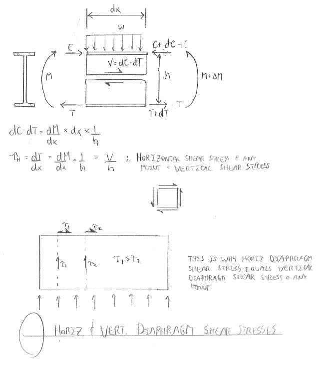
Would love to but I've already posted a custom sketch today and one's my self imposed limit. That whole family feeding thing. The sketch below is related and from when I was trying to convince myself of similar things long ago. Might help.

OP said:
I thought the FBD on the left of my sketch suffices to demonstrate my point of not worrying about the little gap at the ridge (due to ridge vent).

I doubt that anybody every was worried about the little gap that you've addressed, in the sense that you've addressed it. That's just run of the mill drag strut/collector business. The concern that you referenced in the other thread was always all about shear parallel to the ridge.

0P said:
Is it the unit shear (parallel to the ridge, at or close to roof peak) in "wind perpendicular to ridge" load case your concern?

Yesir. Primary concern at least.

OP said:
If that the case, the concerned unit shear would equal V/(building length)? and if the building length is not significant shorter than "W", then it should not of a concern.

I believe this to be incorrect. Horizontal shear equals vertical shear at all locations. It's that whole complementary shear stress business that I mentioned before: Link. My sketch should also help with this.

c01_jzf52n.jpg


I like to debate structural engineering theory -- a lot. If I challenge you on something, know that I'm doing so because I respect your opinion enough to either change it or adopt it.
 
Yes I totally agree with you on horizontal shear in beam and am familiar with it (especially when designing built-up girder and/or reinforcing existing I-beam with plates)

However, we are talking about diaphragm and horizontal beam is its analogy. I am not sure if it is appropriate to utilize the whole shear topic of beam to exam/explain the diaphragm shear problems

I thank you everyone for the response especially Mr. KootK for your interest in the topic with great patience and enthusiasm.

Regards
 
OP said:
I am not sure if it is appropriate to utilize the whole shear topic of beam to exam/explain the diaphragm shear problems

Why would you think otherwise? Per my derivation above, it's based on nothing more than the requirement of equilibrium. Note also that, when we design wood and steel deck diaphragm fastenings, we always design for the same shear in both directions. Your side lap and support fastenings go together as a matching pair. This is why.

I like to debate structural engineering theory -- a lot. If I challenge you on something, know that I'm doing so because I respect your opinion enough to either change it or adopt it.
 
Flexible diaphragm (wood) does not distribute shear to (perpendicular to load direction) shear walls. Hence there is no shear that direction. One will not design wood shear wall (in plane shear) for wind perpendicular to shear wall.

Rigid diaphragm: yes

 
Flexible or Rigid, the diaphragm still acts like a beam whether you want it to or not.
 
hdn32 said:
Flexible diaphragm (wood) does not distribute shear to (perpendicular to load direction) shear walls.

Just because the horizontal shears (perp to load) don't directly load the resisting shear walls doesn't mean that they don't exist within the diaphragm. This is one of the reasons that we have diaphragm chords: to balance the horizontal shears at the diaphragm edge where there may not be shear walls running parallel to that edge.

Besides, if these horizontal shears don't exist in flexible diaphragms, then how do you develop axial forces in your chords?

I like to debate structural engineering theory -- a lot. If I challenge you on something, know that I'm doing so because I respect your opinion enough to either change it or adopt it.
 
@jayrod: yes you are correct.
But the distribution of shear from diaphragm to which shear walls would depend on diaphragm types.
 
Correct, but that is a different discussion than the one you are having with KootK. The horizontal shears still exist, they are just resolved internally in the sheathing up to the diaphragm boundaries.
 
OP said:
But the distribution of shear from diaphragm to which shear walls would depend on diaphragm types.

That is correct but has no bearing on the existence of complementary shear.

I like to debate structural engineering theory -- a lot. If I challenge you on something, know that I'm doing so because I respect your opinion enough to either change it or adopt it.
 
Status
Not open for further replies.

Part and Inventory Search

Sponsor