Continue to Site

Eng-Tips is the largest engineering community on the Internet

Intelligent Work Forums for Engineering Professionals

  • Congratulations SSS148 on being selected by the Eng-Tips community for having the most helpful posts in the forums last week. Way to Go!

Wood I-Joist 3

Status
Not open for further replies.

2457F

Structural
Jun 23, 2011
25
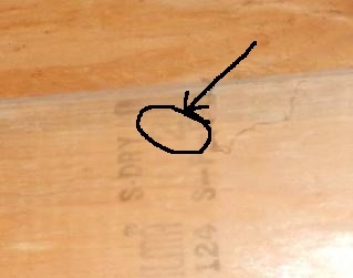
Trying to determine the capacity of some wood i-joist. I have attached a sketch and some photos. The cross-section does not match any wood i-joists from any manufacturer's catalogs. Ultimately trying to post a sign that will indicate the maximum live load. Any ideas? I've never seen 2x4's fastened at the bottom and top chords as can be seen in the photos.
 
 http://files.engineering.com/getfile.aspx?folder=a39cd1e0-c883-4b46-8601-d7d6e11b7d9b&file=Sketch.pdf
Replies continue below

Recommended for you

Can you tell if these are pre-manufactured or could they possibly be someone's homegrown invention?
Is there any grade/species stamp on the 2x4's? Any stamp on the plywood web?

For these to work the nailing between the two top 2x4's to the top of the plywood web (and to each other) would have to be done to develop the horizontal shear between the 2x4's and the web.

I can't recall ever seeing any manufacturer's products that look like that - so my guess at this point would be home-grown I-joists.


Check out Eng-Tips Forum's Policies here:
faq731-376
 
I strongly believe it is someone's concotion. I have never seen anything like this either. I reached out to RedBuilt whose technical representative said he had not seen something like this before. I've reached out to Louisiana Pacific and am waiting a response. The only stamps I could see where on the photos that were attached. The sheathing is 15/32", the grading agency was ILMA, moisture content is dry, and the species of the 2x4 is S-P-F. Without knowing the grade of the wood I can't run an analysis without making assumptions (e.g. assuming the weakest grade of Spruce Pine Fir), correct? Furthermore I do not know the type of fasteners that where used (e.g. common/box/sinker/wood screws etc... I'm leaning towards informing them that not enough information is known and that the only 2 options would be to replace these wood i-joist with a proprietary wood i-joist (this floor structure is small) with known and accepted load values or retrofitting the existing to support the floor live wood (e.g. not counting on the existing wood i-joist system). What do you think?
 
You have another option - perform a load test on the floor.
Reference IBC Chapter 17 I think. This takes some work and planning (and money) to do but might be much more beneficial and less expensive than replacement.

What is the intended use of the floor. It may be that a load test would "probably" at least give you 40 psf live load capacity but that would have to be confirmed.


Check out Eng-Tips Forum's Policies here:
faq731-376
 
2457F - Before going to a load test, work this problem backwards.
What live load is needed?
For now, assume the connection between 2x4's and plywood is adequate. Compute the moment of inertia and section modulus of the composite beam.
Calculate what the stress in the beam is for that live load. At that point, let's see what values you get before taking any more steps.

Those beams look too good to give up on.

[idea]
[r2d2]
 
SlideRuleEra - agreed. But I was going off the assumption that there was no way to verify the nailing between the web and 2x4's.
Without that info - calculations are just pie-in-the-sky.


Check out Eng-Tips Forum's Policies here:
faq731-376
 
2457F:
There are some grade stamps, manuf’g. stamps, on both the web plywd. and the 2x4 flgs. in the photos, but I can’t read them. Maybe a further inspection would be in order to try to pin the material grades down. There might be different grades btwn. the t&b 2x4 flg. material, with the better grade being in the bottom flg. When was this structure built? That would help pin down the allowable design stresses for a given grade. The photos certainly don’t show many (any) screws or nails that I can see, maybe a couple, nails btwn./through the flgs. and the webs, but no crimped nails. So you better determine what you can about the glue used btwn. the 2x4 flgs. and the webs, and how well those joints were clamped and made up. Any butt joints in the web plywd. had better be near the center of the beams/jsts., where the shear is fairly low. These will be weak points in the webs, but could be improved by applying vert. 2x blocking (or plywd.) on either side of the web, in the same vert. plane as the 2x4 flgs. There better not be any butt splices in the bottom 2x4 flg. pieces, and any in the top flgs. had better be very tightly fitted. These butt joints could be finger jointed and glued, but this is not likely in any home made, site built, jsts. You’ll have to rationalize some glue shear design values with wood design codes which don’t have much in the way of any design guidance or automatic approval of same. I agree with SRE, his suggested approach is the first step I’d take. As another first pass at an allowable cap’y., I’d take a look at a current I-jst. table for 14" or 16" deep jsts. on that span length; make some quick adjustments for allow wood design stresses; but also recognize that you have about twice the t&b flg. material and glue area as that provided by today’s tabulations and manuf’g. methods.
 
if you can't confirm the fasteners, you can just specify they add more fasteners to the point where you are comfortable. I'm sure this would be preferable to removing and replacing the joists.
 
2457F - Ok, I've got my numbers (based on some assumptions), what are yours?

Specifically:

Uniform Dead Load
Uniform Live Load
Moment of Inertia of the composite beam
Section Modulus of the composite beam
Modulus of Elasticity of SPF and Plywood
Maximum bending stress
Maximum deflection

[idea]
[r2d2]
 
1. like others have said, they do look pretty good, and 20' span, 16" oc 15" deep sounds pretty good.
2. What is your loading condition, residential?
3. 20' length chords might be single piece; the presence of finger joints would indicate a manufacturing process more sophisticated than DIY.
4. I have seen this system before, maybe 20-25 years ago, I'll look around. I think it never took hold because it is less economical than present modern Ijoist manufactured systems, cheaper manufacturing equipment needed, but less economical utilization of materials: a) The chord orientation doesn't quite get the maximum benefit of the Ixx and Sxx available by orienting the chords flat, and b) the web/chord connection uses more plywood than the contemporary grooved flange to web connection does.
5. Regarding rationalizing the flange-web connection, consider this. Your system has essentially 7 square inches of glue bond per lineal inch of joist. contemporary IJoists have somewhere around 1.5 square inches per inch.
6. You might take samples to review 2 glued joints. a) out of the web around midspan to investigate the joint between edges of 4' wide sheets of plywood. Maybe a 2" circle cut midheight directly over the plywood joint midspan. Is the joint Butt joined or some kind of scarf joint. Is it glued? Some kind of scarfed joint and glue indicates sophistication. b) maybe a sample of the flange to web joint near the support where the moment approaches zero.
7. a glue bond test might be to break a bond and observe it. If the break is clean, than this might suggest that the glue bond is weaker than the inherent strength of the wood. If there are wood fibers present in the glue after breakage, indicating that wood fibers had to be torn out of a wood piece to accomplish the break, this would suggest that the glue bond is stronger than the wood, and that the strength of the wood governs, which I would expect to be the minimum criteria of any properly manufactured structural glued joint.
 
I didn't see any sign of glue at the joints - did anyone else see any?

Also - I think I see a big "2" on one of the 2x4's:

aaaNo_2_fnrhvr.jpg


Check out Eng-Tips Forum's Policies here:
faq731-376
 
JAE - To my eyes, that is definitely a "2". There is another photo that shows a second grade mark with a "2". The grade stamp from the "Interior Lumber Manufacturers' Association", their web page shows that the "2" we see in consistent with Grade No. 2:

I believe there is some glue visible in your photo, and on others. Look at the gray line at the joint of the 2x4 and plywood in your photo. Looks like these composite beams were carefully constructed.

Hope the OP gets back with us, my calcs point in an interesting direction.

[idea]
[r2d2]
 
looks like a too to me 2.
I am ass-u-ming glue, but, .. shrugs...
I'm not sure how they could be mechanically fastened without such fasteners being readily visible; and, if the one or to, too two 2 II visible fasteners are all that exist, well, then it seems to me the whole system is really being supported by just the top chord, and that's if they were top chord bearing, (which I don't know how they would do either....) Perhaps the visible fasteners were utilized to hold the system in place while glue hardened? But I agree that they look carefully constructed and I too would be reluctant to abandon them without further investigation.

Very interested in seeing your calcs Mr SlideRuleEra [yoda]
 
Triangled - Not seeing fasteners is a good sign to me. That tends to indicate that not only is there glue, but a lot of glue. As I mentioned last night, fasteners (screws) can be added... glue can't. The Forest Products Lab has done some very long term defection tests (15 years) on assorted wood truss connectors. The best, by far, were nailed & glued wood gusset plates. Of course, no trusses here but the loads on the joints are similar. Without (expectation of) glue being present, I would not be as optimistic about saving these beams.

Will be happy to share the calcs... later. I want to hear from the OP next.

[idea]
[r2d2]
 
How is the floor performing? Someone needs to take a drill and remove a 1 1/2" or 2" plug to see about the glue between the chords and ply. That will be the make or break decision for these joists. There is a lot of wood in this profile, so I agree with SRE.
 
Hello all. Great responses. I haven't had a chance to jump back on this....this is a back burner project for me. Working on it whenever I have time. I will run numbers soon and post so SRE can compare with my numbers....shouldn't take to long...I'm also interested to see what we both came up with. The joist are bottom bearing. I plan to go back out to the site next week to further investigate. This is an indoor platform that the owners wishes to use as a storage area for misc. items (e.g. filing cabinets (some full/some empty), office chairs etc.). Thanks again for the input....very, very helpful. Will keep this thread updated.
 
...the owners wish to use as a storage area.....OK- then per code that is 125 psf for light storage...unless you post a lower live load.

The problem always is - does the Owner take it upon themselves to monitor the actual weight of stuff on the platform over time?...over 10 years?
And a lot of Owners can't usually perceive what 50 psf is vs. 125 psf.


Check out Eng-Tips Forum's Policies here:
faq731-376
 
JAE... yea, concerned me too... Lay peeps can't tell diff between 50psf and 125 psf, or whatever psf
I did a computer server room conversion for the State somethingorother office and had to specify signage posting maximum LL somethingorother and always wondered who would make that calculation. But, The Sign Said...
 
Hope the OP will continue to work on this problem, but since it may drag on for a couple of weeks I'll "spill the beans" on my first order approximation. Composite beams with plywood webs are devilishly tricky, especially in shear... and this one has some problems. The biggest issue is a plywood web's internal plys... they are oriented the wrong way, just inherent to how plywood is made. The fibers can fail by rolling inside web, and the allowable "rolling shear" stress is lower than the "horizontal shear" stress. That's why manufactured I-joists use OSB for the web instead of plywood.

Here is the "Executive Summary" of my look at this problem:

Bending stress is really low, would likely be acceptable up to the 80+ PSF live load range.

Deflection is low, also. Also good up to 80+ PSF.

Shear is another matter... maybe ok in the 20 to 25 PSF range. This needs to be checked in much more detail than I have done. Even at that loading, the ends of each beam will need additional webs for the point reaction loads at the supports. It is not a big technical issue to add them, but could be an economic consideration.


An example of how elusive solutions to beams with plywood webs are:

I looked in my copy of the standard text on everything wood, Breyer's "Design of Wood Structures" (Third Edition). On the subject of plywood box and I-beams, he "punted". Uses about a page to say "just do what the American Plywood Association (APA) tell you".

2457F - I do encourage you to follow through on your calcs, and I'm sure all of us will be happy to review them. Also, I'll post mine at any time you request. Problems like this, where things don't work out easily, are the absolute best way to get meaningful experience.

[idea]
[r2d2]
 
Status
Not open for further replies.

Part and Inventory Search

Sponsor