Continue to Site

Eng-Tips is the largest engineering community on the Internet

Intelligent Work Forums for Engineering Professionals

  • Congratulations KootK on being selected by the Eng-Tips community for having the most helpful posts in the forums last week. Way to Go!

Wood joist ends are up to 1 inch short of new beam 1

Status
Not open for further replies.

EcoGen

Structural
Dec 8, 2020
59
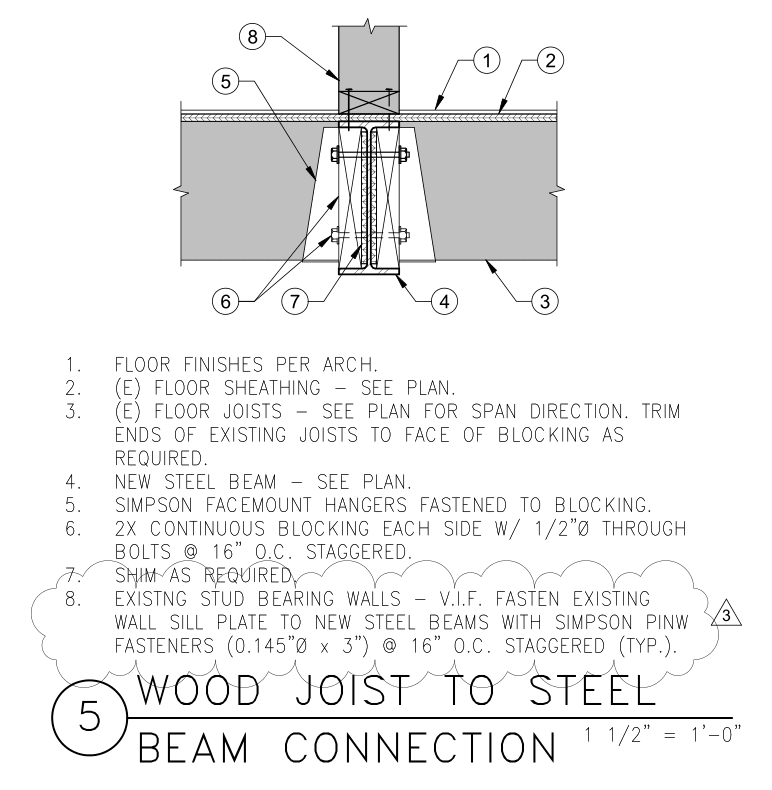
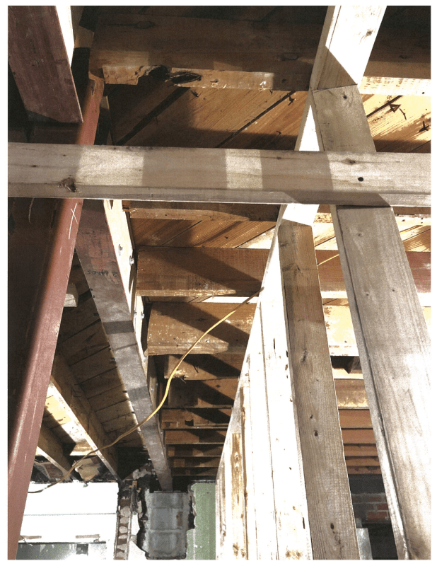
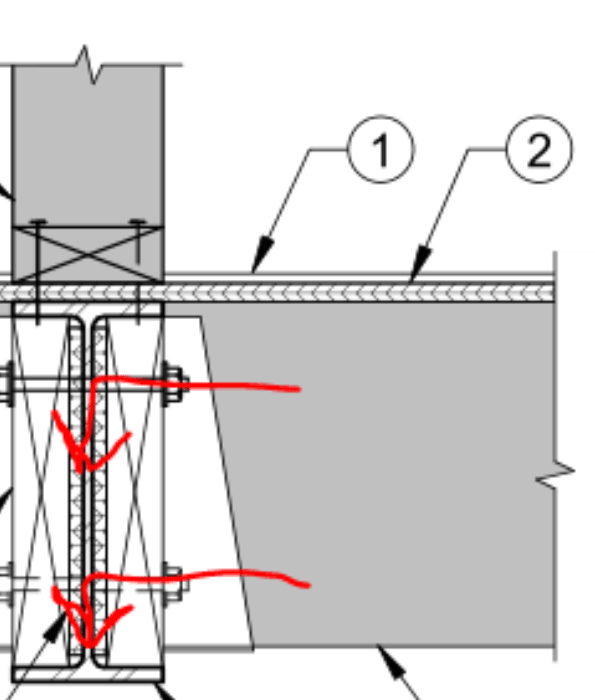
We designed a new steel beam to replace a wall. The existing joists are to be re-attached to the steel beam per detail 5 which shows 2x infill blocking. After installing the steel beam and it's wood section infill, the Contractor has sent an RFI stating that the ends of the existing joists are too short to attach as shown in our detail. I'm guessing they trimmed the joists too short after removing the wall. I believe the joists are 2x10@16"O.C. and the beam is a W10x19.

Here are some of my thoughts on a solution:
[ol 1]
[li]Remove all of the thru bolts space at 16 in on center to remove the 2x blocking and re-install thru bolts with new 3x blocking. And make sure joists are trimmed exactly to fit. This kinda seems like an overkill since this occurs for about 60 foot of the steel beam support.[/li]
[li]Sister in joists to bridge the gap. This definitely seems like an overkill since you would probably have to sister 3 or 4 feet of the joists with a whole bunch of fasteners I imagine.[/li]
[li]Install some sort of ledger to support bottom of joists, but I'm not sure how this would look or how it would attach to our steel beam?[/li]
[/ol]

How would you re-attach ends of wood joists that are short of their support member like this?
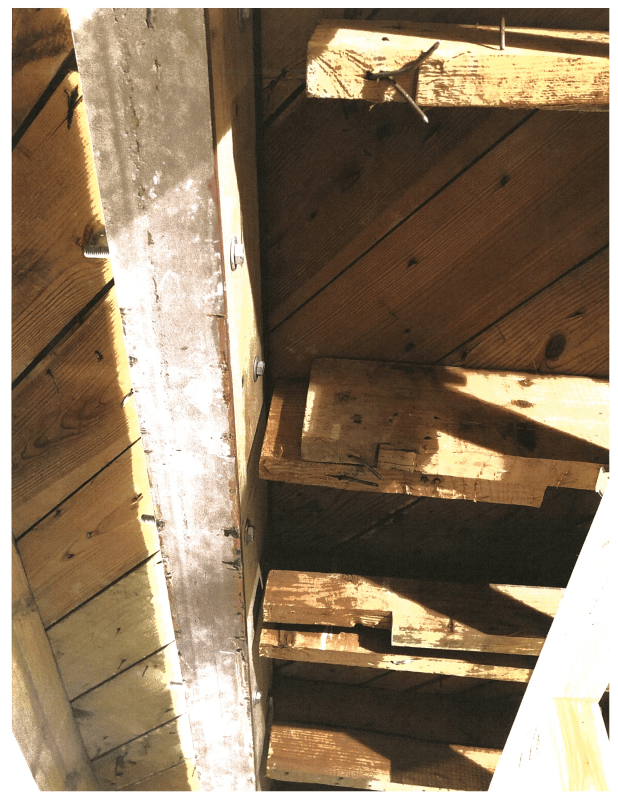
Joists_short_of_support_amfhet.png


Original_Detail_hcnfbf.png
 
Replies continue below

Recommended for you

trim them back a bit further and put in a second beam (should be at the contractors cost)?


Extending the joists is a bit of a fools errand, you'll never reinstate them to the original detail.

 
Yeah...some key information is missing. Like how the beam wound up in the wrong spot? Surely the joists didn't move, and they were supported before. So it sounds like somebody screwed up. I'm not saying to not be a team player, but I agree with Agent666 - extending wood joists is not something that's easily done, and it's never done well.

 
Looks like the beam is loaded from one side. Adding another member to the side will increase the eccentricity and it may rotate. I would sister back as far as you need to for the shear and moment.
Probably only 24" would do.
 
Thanks everyone for the quick replies!

Agent666 said:
trim them back a bit further and put in a second beam (should be at the contractors cost)?

Hmm not sure if a whole new steel beam with blocking and embedding at the ends into existing CMU wall again is going to be cheaper. I'm still waiting on more information from the contractor but we have up to 45 joist ends with this condition. If it's only a few then sistering may be the way to go cost wise. Otherwise I'm thinking of removing the 2x blocking and installing 3x blocking, which is also a lot of work.

phamENG said:
Like how the beam wound up in the wrong spot? Surely the joists didn't move, and they were supported before. So it sounds like somebody screwed up.

I took on this project from someone who's already left our office so I don't have the entire picture figured out yet. One possibility is that the wall that was removed was an 8 inch thick CMU wall and now the new W10x19 beam is only 4 inches wide. The joists may have just been pocketed into the wall shy of 2 inches. Again I'm not certain of the 8 inch CMU wall and have put questions out to the Contractor to figure out what happened. Will keep you posted on the results.

XR250 said:
Looks like the beam is loaded from one side. Adding another member to the side will increase the eccentricity and it may rotate. I would sister back as far as you need to for the shear and moment. Probably only 24" would do.

That's a good point, the torsion on the beam is something I haven't considered. Not sure if the original designer even considered it. But since it is wood framed floor framing into a steel beam, I don't think there would be a whole lot of torsion on it. Sistering may be the way since it's probably going to be the cheapest. I need to read up on how to design sistered splices effectively and optimized. Any design sources or example suggestions that you usually use?
 
Based on my conversation with the Contractor the joists are actually 3/4" to 2-3/4" short of the support - not one inch! Below is what I've sent out to our client (the Architect). Let me know what you guys think. I'll keep you posted on additional information.

My understanding is that the majority of the joists have been cut too short by the Contractor and that is why they are now short of the beam support. Because of this, detail 5/S-500 cannot be installed as shown. There is no easy solution to re-support the ends of these short joists. Some of the options we have thought of include the following:

[ol 1]
[li]Doubling up joists so new reinforcing joists are cut to the correct distance to bridge the gap. Probably about ¾ of each joist’s span would need to be reinforced (to be verified with calcs). Then cutting the old joist back far enough to allow a single-joist hanger attaching the end of the new reinforcing member to the beam blocking.[/li]
[li]Welding a continuous steel plate to the bottom of steel beam’s bottom flange. Then shimming above the plate to allow all joists to bear on the plate. This would result in an eccentric connection to the steel beam and would likely require (to be verified with calcs) some additional blocking parallel to the joists on the other side of the beam to brace the beam from torsion.[/li]
[/ol]

 
If it were me, I would just cut the joists back to a consistent length, and ledger a new block to the web filler on the steel beam. With the thickness of the ledger to match the short cut length of the joists. Now you can hanger off the ledger and problem solved.

Similar questions have come up before on these forums, and put me firmly in the camp of not trusting nor relying on the development of a moment connection in wood to try and splice a short member and make it longer. Always keep in mind that load follows the stiffest path, and mechanical connectors are nearly always less stiff than the wood itself, so it's unlikely that the moment connection will engage prior to local member failing, unless the mechanical connection is a long epoxied length or some other exotic connection that develops sufficient stiffness.
 
Are you certain the existing condition wasn't something like this:
Capture_zgbnql.jpg


I've only seen it done this way a handful of times but the framing seemed to be laid out this way to try and alleviate the deflection differential between adjacent spanning joist and bearing point.

I'm making a thing: (It's no Kootware and it will probably break but it's alive!)
 
EcoGen said:
Doubling up joists so new reinforcing joists are cut to the correct distance to bridge the gap. Probably about ¾ of each joist’s span would need to be reinforced (to be verified with calcs). Then cutting the old joist back far enough to allow a single-joist hanger attaching the end of the new reinforcing member to the beam blocking.
Welding a continuous steel plate to the bottom of steel beam’s bottom flange. Then shimming above the plate to allow all joists to bear on the plate. This would result in an eccentric connection to the steel beam and would likely require (to be verified with calcs) some additional blocking parallel to the joists on the other side of the beam to brace the beam from torsion.

I doubt you would need to go back that far to sister. 4 ft. and some poly subfloor adhesive and you will be fine. I don't agree with ChorasDen on this. I would not go route #2. The blocking will never be installed tight enough to do any good.
 
Ahh, I missed the lower wall on the right of the photo when I first opened this post. What is the purpose of this wall? You mentioned in the OP that the original wall supporting the joists has been removed by the contractor. Celt83 may be onto something with that detail.
 
I would guess that wall is the temporary support of the joists while they install the beam.

I tend to agree with XR250 on this one. The amount of moment that the sistered splice would need to transfer is relatively small, I don't see how any significant rotations/deformations could develop due to fastener slip and cause major issues before that moment is resisted (assuming appropriate qty/size fasteners are used at each end of the splice).
 
ChorasDen said:
If it were me, I would just cut the joists back to a consistent length, and ledger a new block to the web filler on the steel beam. With the thickness of the ledger to match the short cut length of the joists. Now you can hanger off the ledger and problem solved.

We discussed this in our office and it's not going to work. They will essentially run into the same problem again. They won't be able to properly install the ledger to fit because the ends of the joists would be in the way. It's hard to visualize the constructability issue but the image below might help. Unless we detach the steel beam, install the correct size wood ledger, and then put the beam back where it's supposed to be.

Celt83 said:
Are you certain the existing condition wasn't something like this:

See below for an image of what the demolished wall below this support line used to look like. You can see that the joists are one piece and extend over the wall. So they definitely just cut the ends of the joists too far back. In hind sight, the detail we provided (see my first post in this thread) was not a good detail. It's not very practical but the Contractor should have made us aware of the potential constructability issues before cutting all the joists. A top-bearing hanger would have been a better detail.

XR250 said:
I doubt you would need to go back that far to sister. 4 ft. and some poly subfloor adhesive and you will be fine.

The wood expert in our office thinks that only 4 feet will not work. I haven't run any calculations myself yet. Adhesive is an iffy subject in our office. We typically believe we have to prove with calculations that mechanical fasteners will work and then you can add adhesive to make yourself feel better afterwards. Do you have any examples or design guides on how I would design an extension like this and what kind of nailing would be sufficient?

ChorasDen said:
Ahh, I missed the lower wall on the right of the photo when I first opened this post. What is the purpose of this wall?

That wall is most likely temporary support holding the existing joists up.

dauwerda said:
The amount of moment that the sistered splice would need to transfer is relatively small, I don't see how any significant rotations/deformations could develop due to fastener slip and cause major issues before that moment is resisted (assuming appropriate qty/size fasteners are used at each end of the splice).

I had the same question for you too: Do you have any examples or design guides on how I would design an extension like this and what kind of nailing would be sufficient?
 
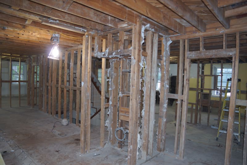
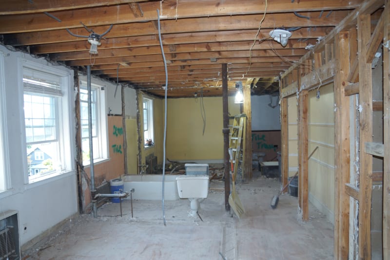
The first two photos below shows the conditions prior to removal of the walls. These are at two different locations but they have the same issues. You can see the joists extend over the interior wall line in both photos. So they definitely cut the joists too short.

The last photo shows a better view of the current condition of the short joists after installing the new steel beam. I believe the Contractor didn't want us to see all this additional information but I had to squeeze it out of them. Take a look at the first photo they gave me in my first post in this thread compared to the photo below. They were trying to tell me that all of the existing joists already needed extensions. Meanwhile when you zoom back a little you see only 1 or 2 had existing extensions and the rest just have been cut short. Also in my phone call conversations they are trying to avoid admitting this at all costs.

DSC03365_zqyqcy.jpg


DSC03063_xsgap4.jpg


current_condition_fblitx.png
 
EcoGen said:
The wood expert in our office thinks that only 4 feet will not work. I haven't run any calculations myself yet. Adhesive is an iffy subject in our office. We typically believe we have to prove with calculations that mechanical fasteners will work and then you can add adhesive to make yourself feel better afterwards. Do you have any examples or design guides on how I would design an extension like this and what kind of nailing would be sufficient?
I was considering the adhesive as a belts and suspenders approach. It likely has more capacity than the fasteners but is not necessary. The fasteners can be easily designed to take the loads. It is a simple statics problem to find the loads in the fasteners. I have not checked but my gut is that 4 ft. would work.
 
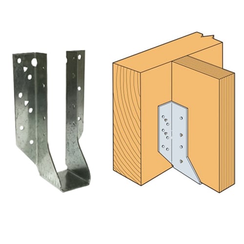
Just my guess, have you tried any Simpson ties to counter the gap or ask them to provide if any custom-made ties are available? Still, there is an eccentricity issue that we need to deal with
simpson_hu7_oek3oe.jpg


Thanks in advance!!
 
EcoGen - I agree with not counting on the adhesive. Even if you have a load capacity for it, the chances of them getting the environmental conditions, cleanliness, clamping pressure and time, and all the other variables just right to achieve those capacities is a pipe dream.

EcoGen said:
In hind sight, the detail we provided (see my first post in this thread) was not a good detail.

I disagree with this. I've used this detail before with no problems. Your bearing conditions may have complicated things a bit, but you only have joists framing in from one side which would have made it easier.

Since they are only framing in from one side...how are they anchored to the CMU at the ends? Any chance they can free it, shift it an inch or two, and then re-anchor it?

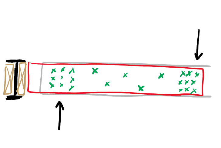
If not, and splicing those joists is the only way....this is how I do it. If you do a quick search here on sistered joists you'll find this method championed by KootK in several threads. I'm pretty sure I got it from him. The trick is to not resist the induced moment directly. You want to break it out into direct shear forming a couple to resist it. So you'll have a group of screws at each end and periodic screws along the length. The statics analysis is similar to a telescoping tube.

Screenshot_2022-03-02_074503_pkakdu.png
 
@Veer007 this is the connection we have shown in the detail in my first post of this thread. Simpson states a maximum of 1/8" gap. We have gaps ranging from 3/4" to 2-3/4". If this vonnection could work, I wouldn't be too worried about the torsion since most of the load is transfered to the beam web via the 2 through bolts. But if we were to bear the joists on a plate welded to the bottom flange, then I'd say the torsion is more of a concern.


EcoGen Consultants
Structural Engineers
ecogenconsultants.com
 
EcoGen said:
We have gaps ranging from 3/4" to 2-3/4". If this vonnection could work, I wouldn't be too worried about the torsion since most of the load is transfered to the beam web via the 2 through bolts.
I would be very worried about torsion. Stick with sistering. Also, specify that the existing joists be cut back enough to allow the new hangers to be installed without interfering with the seat.
 
Since you only have joists one side, can you shift the beam over, or do you have load bearing above?
 
phamENG said:
but you only have joists framing in from one side which would have made it easier.

You're right actually. The detail we provide should have worked fine for the one sided joists if they had planned ahead correctly. But I wouldn't use this detail for existing joists on both sides in the future. I feel like it would be impossible to cut the joists on both sides exactly to 1/8" tolerance to shove this new steel beam in. Top bearing hangers could make it a little easier since even if there was any sort of gap up to 1 inch, I would just fill it in with blocking and not worry about it.

phamENG said:
Since they are only framing in from one side...how are they anchored to the CMU at the ends? Any chance they can free it, shift it an inch or two, and then re-anchor it?
JStructsteel said:
Since you only have joists one side, can you shift the beam over, or do you have load bearing above?

These are good points and an option I haven't considered. I do not think any of the beams that have this issue have a load-bearing wall above them but I'll make sure they verify in field before proposing this option.

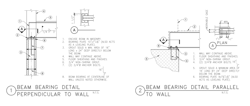
See the bearing detail we provided for the steel beam. They also fully grouted the CMU cells. So it would mean cutting anchor bolts, relocating base plate, maybe some more grout, then using post-installed anchors to re-embed into the CMU wall.

End_bearing_detail_lw9l3l.png


XR250 said:
I would be very worried about torsion.

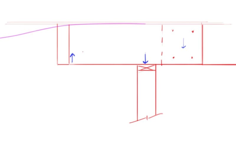
See below for the load path that someone in my office claims will occur and that's why they are not as worried about torsion. If there were no through bolts and the joists were bearing directly on the edge of the bottom flange I would definitely agree that there is torsion to worry about. Not too sure what to think with the thru-bolts in place myself though. I just tried drawing a free body diagram and it seems like the through bolts would just push the blocking on the one side down and the blocking on the other side up. Essentially resulting in torsion again, globally.

load_flow_2_desasy.png


EcoGen Consultants
Structural Engineers
ecogenconsultants.com
 
Status
Not open for further replies.

Part and Inventory Search

Sponsor