Continue to Site

Eng-Tips is the largest engineering community on the Internet

Intelligent Work Forums for Engineering Professionals

  • Congratulations waross on being selected by the Eng-Tips community for having the most helpful posts in the forums last week. Way to Go!

Wood shear panel modeling in FEA program 3

Status
Not open for further replies.

struc_eng

Structural
Mar 24, 2017
11
Hi all!

Need some help in wood panel wall model design process. Does anyone tried to make something similar ?
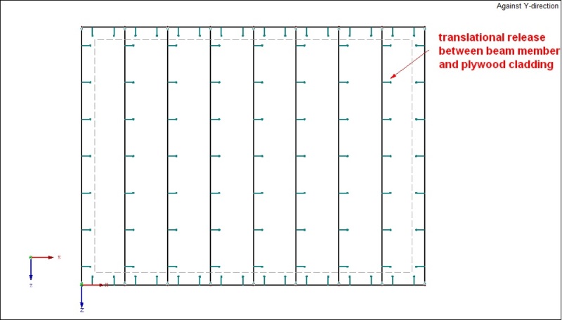
For the beginning i'm started with beam frame design and plywood cladding in 2D modeling environment to
understand is it possible to design something like that at all... and right way faced with problem.
If i want to design panel easy as possible, but in same time precisely and close to reality, i have to figure
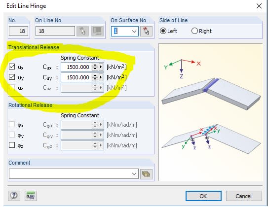
out how to design fasteners in most simple and efficient way. In program i can add spring constant between frame beam and plywood
cladding like translational release. Spring constant is measured in Kn/m2. Question is can i use it to simulate
functioning of fasteners and how to calculate it ? Or maybe there is any more simple way to do it ?

Any help will be highly appreciated and sorry for my english.
Thank you!
 
Replies continue below

Recommended for you

So, you want to create and FEM model that includes the plywood sheathing, the wood framing members and the nailing. I'm sure it can be done, but only if you're writing an academic paper on the subject. This just isn't the sort of thing you want to do for design work.

For design work, I would recommend using a plate FEM model based exclusively on the sheathing. Then you can modify the shear modulus based on the "apparent shear stiffness" (Ga) concept from the NDS special design provisions for wind and seismic (SDPWS). Even that can get relatively complex...
 
Yes, i'm structural engineer and i'm working on this project to find out how to get internal forces end deformations of wood frame shear wall. That is why i want to start with simple 2D panel calculation at first and maybe more complex 3D later. But the goal is not to model perfect 3D panel with all detailing. The aim is to get result in most simplest way. Because i have to make simple 3D building from panels later.
 
I'm curious about this issue too. Not sure if I am looking for the same type of answers that you are? Mainly I want to place a wood stud wall "element" into a frame model for single family residence building analysis.
Beams and columns are straight forward enough but load bearing wood stud walls with plywood (or not) are more troublesome.

What program are you using to model?
 
I don't see the reason why you are going to such great lengths for a single family residence shear wall. I work in Southern California, primarily on custom single family homes and I really don't see why you are modeling this in FEM. What are your concerns?

I have done many many remodels on very old houses, 1940's to 1950's that have been through earthquakes and they are still structurally sound and they don't even have shear walls with plywood. Only exterior stucco walls.
So let me ask you something, if you determine that the end deformation of the shear panel is just a little to much in your model I am assuming that you may increase the shear wall stiffness or utilize a different system, is this correct? Have you considered what this actually means in "reality"? If this is done for the entire lateral force resisting system on a single family residence the house will be too expensive to build.
 
Challenge is to understand how to add or simulate screws or nails in such a panel, as they are the most important part of panel. I have found information in internet resources how to simulate fastener behavior with springs, but it's to complicated and takes a lot of time to model and define settings for every single fastener. Even more if you try to model for example 3-storey building.

=> HouseBoy I'm working in Dlubal RFEM program.
 
For model i made a beam member frame and plywood sheeting. In program there is an option to add translational release between wood stud and plywood sheet as a spring constant. But i have to calculate it somehow... see pic below. And i'm not convinced that this is the right solution.

panel_1_zbue7n.jpg

panel_2_iscz4g.jpg

panel_3_pcvze4.jpg
 
Okay, so I used to work for RISA and was deeply involved in their creation of an FEM based FTAO wall analysis / design. My thoughts on this subject and on RISA's implementation:

1) I totally understand the desire to do this via FEM. If only to validate the many (sometimes dubious) assumptions made during your hand calc.

2) The desire is to replicate traditional design concepts. That means using the studs only for resisting gravity loads, and the sheathing only to resist shear. It also means OTM is resisted exclusively by the chords / hold downs.

3) The problem is that these traditional assumptions don't really match up with a complete FEM analysis of studs, sheathing and nailing like you are trying to do. That coupled with the fact that your model will be incredibly complex.

4) The solution (at least when RISA implemented it) was to use a simpler FEM model. Then use this model to pull out results that could be used for the design of studs, sheathing and such.

5) The model consists primarily of an orthotropic plate element whose shear stiffness was based entirely only the sheathing (adjusted for the nailing by using NDS Ga values). The vertical stiffness and out of plane stiffnesses of the plates were based on the studs.

6) When the FEM analysis was run, you get large shear stress risers around the openings and such. Instead of using the max shear, the average shear stress over the area of each "block" was used for calculating the shear demand in that block.

7) Then to get strap forces, we run the "internal force summation tool" to look at the moments between adjacent blocks. And, use those moments to design the straps.

8) Lastly, the same thing was done at the bottom of the wall to come up with hold down / chord forces.

I'm in the early stages of writing a paper comparing the RISA method for FTAO to traditional hand calculations. But, it's something that's moving very slowing since I'm doing it entirely in my free / after work time.

In my opinion, this method works really well for a single wall. Much better than hand calcs. That's because it is produces a design that always obeys statics and is consistent with it's own assumptions. The hand calc method rely on a number of dubious assumptions about points of inflection and such. Maybe those assumptions are valid for walls with simple and symmetric geometry. But, the more complex the geometry the worse those assumptions become and the harder it is to justify your hand calcs.

Now, if you're putting together a whole building, I'm not so sure that the FEM model is quite as useful / accurate. At least not without some adjustment. The problem is that the FEM stiffness of the individual blocks within a wall is totally reasonable and consistent for determining the forces within the wall alone. However, the assumed stiffness of the overall wall (based on NDS / APA equations) doesn't quite line up with what you get from the FEM model. Therefore, when you have multiple walls or combine wood walls with moment frames or masonry walls or whatever, the relative stiffness of these would walls would have to be adjusted to match the NDS / APA equations. If not, then the force distribution between lateral force resisting elements may not be what you want it to be.
 
Status
Not open for further replies.

Part and Inventory Search

Sponsor