masterdesign
Structural
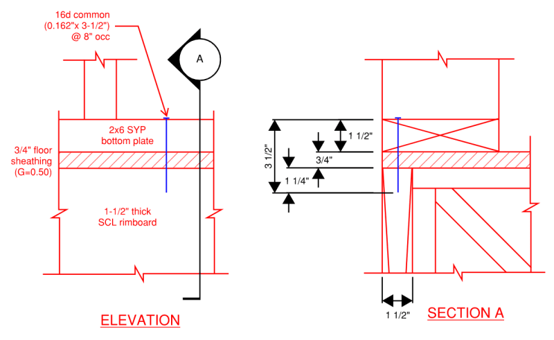
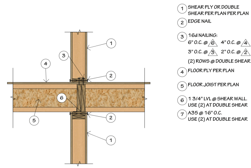
I’d like to get opinions on the shear transfer of an upper wall into the floor system at the exterior of a multi-story building (2-5 floors), using bottom plate nailing only.

The nail is in single shear with the bottom plate as the side member. In order to design the nail per NDS Table 12N, assume floor sheathing acts compositely with rimboard as main member.
Nail capacity = 141 # (NDS Table 12N)
Connection capacity = 141*1.6*12/8 = 338 plf
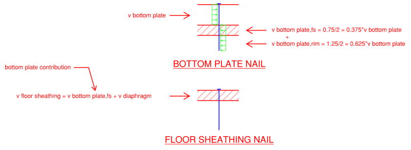
The connection of the floor sheathing must account for the composite action.

Assume
[ul]
[li]Floor sheathing nailing = 10d common (0.148”x3”) @ 6”[/li]
[li]Demand = bottom plate contribution + diaphragm contribution[/li]
[li]Diaphragm construction factor (1.1) applies to fastener capacity[/li]
[/ul]
Nail capacity = 95 # (NDS Table 12Q)
Connection capacity = 95*1.6*1.1*12/6 = 334 plf
v bottom plate,fs = 0.375*338 = 127 plf (bottom plate contribution)
max v diaphragm = 334-127 = 207 plf
Therefore, you would be limited to 207 plf diaphragm shear when transferring 338 plf bottom plate shear using the bottom plate nail alone. If my goal is to have a single design that can be used throughout the structure, I don’t see this working without additional specification (wall sheathing lap, hardware or drag), since my diaphragm shears are quite frequently over this limit.
I know additional specification (wall sheathing lap, hardware or drag) can make this work. I am specifically looking at using the bottom plate nailing alone to contrast my experience. I have seen this detail used regularly by Engineers, including at firms I have worked for, across multiple floors. I just don’t see how the numbers work without additional specification.
Lastly, an alternate option which avoids putting increased demand on the floor sheathing is to neglect the floor sheathing in the design of the bottom plate nail and assume there is a gap between the side member (bottom plate) and main member (rimboard). This fastener design condition is covered in AWC TR12.
Nail capacity = 48 # (calculation omitted for brevity)
Connection capacity = 48*1.6*12/8 = 72 plf
This method is quickly ruled out since most shear demand will be much higher than this.

The nail is in single shear with the bottom plate as the side member. In order to design the nail per NDS Table 12N, assume floor sheathing acts compositely with rimboard as main member.
Nail capacity = 141 # (NDS Table 12N)
Connection capacity = 141*1.6*12/8 = 338 plf
The connection of the floor sheathing must account for the composite action.

Assume
[ul]
[li]Floor sheathing nailing = 10d common (0.148”x3”) @ 6”[/li]
[li]Demand = bottom plate contribution + diaphragm contribution[/li]
[li]Diaphragm construction factor (1.1) applies to fastener capacity[/li]
[/ul]
Nail capacity = 95 # (NDS Table 12Q)
Connection capacity = 95*1.6*1.1*12/6 = 334 plf
v bottom plate,fs = 0.375*338 = 127 plf (bottom plate contribution)
max v diaphragm = 334-127 = 207 plf
Therefore, you would be limited to 207 plf diaphragm shear when transferring 338 plf bottom plate shear using the bottom plate nail alone. If my goal is to have a single design that can be used throughout the structure, I don’t see this working without additional specification (wall sheathing lap, hardware or drag), since my diaphragm shears are quite frequently over this limit.
I know additional specification (wall sheathing lap, hardware or drag) can make this work. I am specifically looking at using the bottom plate nailing alone to contrast my experience. I have seen this detail used regularly by Engineers, including at firms I have worked for, across multiple floors. I just don’t see how the numbers work without additional specification.
Lastly, an alternate option which avoids putting increased demand on the floor sheathing is to neglect the floor sheathing in the design of the bottom plate nail and assume there is a gap between the side member (bottom plate) and main member (rimboard). This fastener design condition is covered in AWC TR12.
Nail capacity = 48 # (calculation omitted for brevity)
Connection capacity = 48*1.6*12/8 = 72 plf
This method is quickly ruled out since most shear demand will be much higher than this.

