Continue to Site

Eng-Tips is the largest engineering community on the Internet

Intelligent Work Forums for Engineering Professionals

  • Congratulations SSS148 on being selected by the Eng-Tips community for having the most helpful posts in the forums last week. Way to Go!

Wood Shear Wall Chord Forces

Status
Not open for further replies.

medeek

Structural
Mar 16, 2013
1,104
I'm sitting here looking at some sample problems for shearwalls from Breyer's book and Malone's book. The question du jour has to do with shearwall chords, specifically shearwall chords in compression.

Let's assume I've got a shearwall that runs the full length of the rear wall (30') of my 24' x 30' garage, single story, slab-on-grade, 4:12 pitch roof, trusses, 10 ft. walls, basic rectangular structure. The roof bearing load on the rear wall due to the trusses is:

S 300 plf
D 204 plf

Assume V = 3000 lbs shear (ASD) due to wind substantially governs, seismic is negligible in this case.

then:

Unit Shear = 100 plf

Basic chord tension compression per SDPWS-2008 (4.3-7):

T = C = vh = 100 plf * 12 ft = 1200 lbs

To be conservative I usually design my holdowns for this tension neglecting any counteracting dead or live loads.

However, the compression in the chord without the bearing loads is not conservative. The question is how much of the uniform bearing load should be applied to the shearwall chord?

Some samples I've seen will apply half the width of the shear panel as the tributary length. However, I don't see this as reasonable when the shear panel is 30 feet long, a lot of that bearing load will actually be carried by the other studs in the wall. In the case where there is a point load (ie. girder truss directly above shearwall chord) the answer seems clear enough but even in this case there will still typically be a uniform bearing load on the shearwall in question and a certain amount of that bearing load should be applied to increase the compressive load in the shearwall chord in addition to any applied point loads and the compressive load due to overturning.


A confused student is a good student.
 
Replies continue below

Recommended for you

First of all, you made a math error. The chord force is 1000 lbs, since the wall is 10' high.

I don't think a wood shear wall behaves as a single unit, so you will not get 1/2 of the gravity load on the entire wall coming into the compression chord. Rather, a wood shear wall behaves as a series of wood panels. Starting at the compression end of the shear wall, as each panel tries to overturn, the next panel holds it down. So--the axial force due to gravity load in the compression chord is just the force on that one stud.

DaveAtkins
 
This is a topic of special interest to me. I've often felt that the presence of unaccounted for axial loads on a shear wall messes with the compression chord force (and diaphragm force for that matter). See the calc below. It's more illustrative when it generates no tie down force.

20150203%20SW%20Compression.JPG


I like to debate structural engineering theory -- a lot. If I challenge you on something, know that I'm doing so because I respect your opinion enough to either change it or adopt it.
 
Here is how I would solve KootK's example:
OTM = 135 KF
RM = 10K(10' + 20' + 30') = 600 KF
RM > OTM
Holddown force = 0

I anticipate a spirited debate[swords]

DaveAtkins
 
Let the games begin! For starters, you need to calc out the compression reaction. We agree on the tie-down force which is not all conducive to a good eng-brawl.

I like to debate structural engineering theory -- a lot. If I challenge you on something, know that I'm doing so because I respect your opinion enough to either change it or adopt it.
 
Sorry I changed the wall height to 12 ft midway through my post but forgot to update the text.

A confused student is a good student.
 
I'm not sure I follow your calculations above, is there an opening between B and C?

The loads on the wall should not affect each others (superposition principle) resultants.

So if my shearwall has studs at 16" o/c then technically the additional compressive force from the uniform bearing load will be at worst 16" of trib. length times the linear load:

D + W = (204 plf x 1.33') + 1200 lbs = 1471 lbs

or

D + .75L + .75W + .75S = (204 plf x 1.33') + 0 + .75 x (1200 lbs) + .75 x (300 plf x 1.33') = 1471 lbs


That was weird, to two load cases coincidentally gave the same answer.


A confused student is a good student.
 
No opening. That was just my rendition of a shear wall label. The point that I was attempting to make was that, if gravity loads resolve the applied moment before you get to the tension boundary element, the lever arm to the compression chord is effectively reduced and the compression load is increased. Just a theory of mine.

I think that the superposition argument only holds if you consider the wall to be a rigid body. Given the shear flexibility of the diaphragm, that's a stretch.

Don't let me distract you from chasing down the right/conventional answer here. The wall is generally treated as a rigid body and the only loads that needs to be resisted by the compression chord are:

1) The moment divided by the wall length.
2) Any load applied directly to the compression chord.
3) A tributary width of uniform load commensurate with the distance to the neighbouring stud(s).

I like to debate structural engineering theory -- a lot. If I challenge you on something, know that I'm doing so because I respect your opinion enough to either change it or adopt it.
 
Ok, I see where you are going with this now. If you treat the wall as a rigid body (solid body lump) and draw a free body diagram of the forces, not allowing there to be a reaction along the sill plate except for at the ends of the shearwalls I believe your argument holds. However, once you introduce the sill plate reaction possibility and let the entire shearwall become a compliant structure I think it becomes and indeterminant structure. I would have to give that some more thought. The addition of large vertical forces would seem to complicate the matter as you suggest.

A confused student is a good student.
 
Here is a slightly related shearwall question.

I've got two panels in my shearwall wall line (9 ft. height, 30 ft. length), one is 5 ft. in length and the other is 3 ft. in length, the rest of the wall is a mix of windows and doors. The aspect ratio of the two panels is 1.8 and 3.0 respectively. One of the panels exceeds the 2:1 ratio for seismic so I have to apply the 2bs/h (.67) reduction factor to the unit shear capacity.

In this situation would it be correct to conservatively assume the reduced capacity for the entire shear wall or would it make more sense to average the capacity between the reduced capacity of the 3 ft. panel and the unreduced capacity of the 5 ft. panel.

A confused student is a good student.
 
What I am suggesting is a weighted average:

3ft. Panel:

b = 3 ft
AR = 3
AR Reduction = .667
Nominal Allowable = 320 plf
b x allowable = 960 lbs

5ft. Panel:

b = 5 ft
AR = 1.8
AR Reduction = 1.0
Nominal Allowable = 480 plf
b x allowable = 2400 lbs

Total (b x allowable) = 960 + 2400 = 3360 lbs

Weighted Average Nominal Allowable = 3360 / (3 + 5) = 420 plf

A confused student is a good student.
 
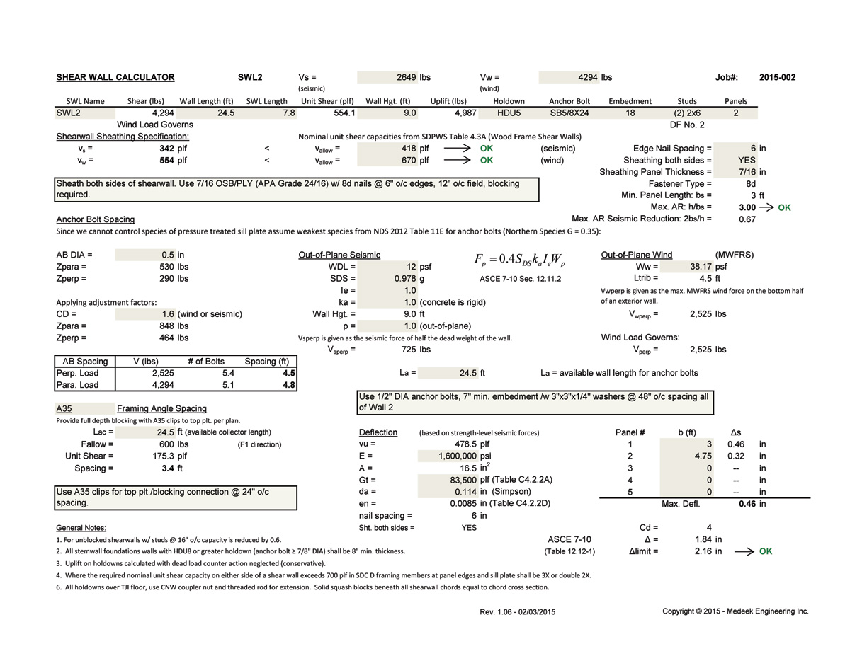
My updated shearwall spreadsheet (two pages) now takes this uniform gravity load into account as well as the ability to handle any point loads bearing directly on top of the shearwall chords:

2015-XXX_SWLXX1.jpg


2015-XXX_SWLXX2.jpg


A confused student is a good student.
 
I would say that Kootk's second explanation is more conventional:

1) The moment divided by the wall length.
2) Any load applied directly to the compression chord.
3) A tributary width of uniform load commensurate with the distance to the neighbouring stud(s).

You could seemingly tackle the problem a number of ways.

1. As noted by above, the 'conventional method'
2. By resolving individual panels for T/C
3. Kootk's first method
4. If you are assuming the wall is rigid why not use a linear stress distribution (P/A + M/S). Then you could have 'multiple' hold downs. Maybe even get the anchor bolts to work. but then you would have cross grain bending (although if yo have washers this has been deemed acceptable).

Hopefully Josh comes out with that white paper on FEM for wood shear walls. Maybe their are other good papers on shear wall behavior.


EIT
 
Nice. Is multiple tie downs a real thing? I've never attempted that. That would effectively reduce the lever arm a tad.

I like to debate structural engineering theory -- a lot. If I challenge you on something, know that I'm doing so because I respect your opinion enough to either change it or adopt it.
 
I wasn't checking the bearing pressure on the sill plate previously and just as I suspected it is near capacity in this instance.

A confused student is a good student.
 
I didn't read through the entire post thread, but here's my two cents:

I use the boundary elements only for the compression and tension forces due to overturning (rigid body assumption). The typical studs in the wall take the loading from the floor/roof above; ie the shear wall boundary element is in addition to the typical wall framing. As for multiple holddowns, Simpson allows holddowns on either side of the boundary element. Hybrid holddowns are also permitted and I've actually got a job right now where we use conventional holddowns on the upper 3 floors and a tie rod system for the bottom level embedded in the concrete podium slab with a plate washer and heavy hex nut. This was due to uplift forces exceeding the capacity of conventional hold downs. For the compression chords, I've found that for 2x6 shear walls crushing of the sill plate will mostly control; whereas compression capacity of the stud/post mostly controls for 2x4 shear walls.

The idea of the wood shear wall actually behaving as rigid has been discussed on here before. I believe AWC is looking into this assumption and there may be some changes to shear wall design in the future (hopefully distant). I think this is a conservative approach and it has worked for decades with no problem, given that proper detailing and design practices were used.
 
These shearwalls can get pretty complicated in reality. Reading through Malone's book this morning on offset shearwalls both vertically and horizontally made me realize I should be thankful that most of my jobs are single story residences and actually quite straightforward.

When connecting chords between floors I've seen both straps and (2) HDU type holdowns used as well as the more elaborate tie rod systems from Simpson. Just wondering what the pros and cons are for each method from other practicing engineers. Recently I've moved away from strap type holdowns that are embedded into concrete (ie. STHD14, STHD10 etc...) for a variety of reasons.

046e-2015.gif


188a-2015.gif


A confused student is a good student.
 
ATS: Anchor Tiedown System

design-ex_CTDS33.gif


A confused student is a good student.
 
There may be more pros and cons to each method, but I've generally found this to be true.

Conventional straps:
Pros - easy to install, no shrinkage accumulation
Cons - relatively low force transfer

Conventional Holddowns:
Pros - Easy to install and applicable to most situations in multistory wood buildings, no shrinkage accumulation
Cons - Can limit spacing of shear walls based on holddown forces rather than shear capacity (multistory buildings)

Tie Rod System:
Pros - Wide range of force transfer, connection to podium slabs for uplift much easier
Cons - Shrinkage accumulation in shear wall, requires shrinkage compensation devices to limit drift, contractors generally prefer to avoid this.
 
Status
Not open for further replies.

Part and Inventory Search

Sponsor