Continue to Site

Eng-Tips is the largest engineering community on the Internet

Intelligent Work Forums for Engineering Professionals

  • Congratulations KootK on being selected by the Eng-Tips community for having the most helpful posts in the forums last week. Way to Go!

Wood shear wall compression chord 2

Status
Not open for further replies.

YoungGunner

Structural
Sep 8, 2020
98
I want to disagree with the Breyer's textbook about including distributed dead loads in the compression force in a chord for a shear wall. Points loads that the chord normally supports vertically yes, but not distributed loads across the entire wall. Here is why:

1. The SDPWS starts by using the same equation for the compression and tension in the chords. For the tension, the code specifically implies in 4.3.6.4.2 that the dead load may be used as a stabilizing moment to reduce the effect of tension. However, the code does not imply anywhere that an increase in the chord forces from that same dead load is required. I assume then, that theory of adding the load to the compression force came from the idea of "well, it was subtracted from the uplift."
2. It makes sense to me that a distributed load would help prevent an entire wall from lifting up on one end. I don't picture the distributed load assisting as if the wall is spanning chord to chord, but that the dead load over each portion of wall provides some resistance to it's own sphere, which ultimately prevents the whole wall from lifting (assume the dead load is enough to prevent uplift). However, to say that these vertical forces are amplifying the chord forces would imply that the wall has to span chord to chord - but the wall is much too flimsy to do that. The vertical distributed dead load remains supported by the distributed series of studs and headers, so it feels unnecessary that the chords would suddenly experience that force as if the studs weren't present.

Anyone want to provide additional insight?
 
Replies continue below

Recommended for you

driftLimiter said:
But at KootK's behest, they are using it for reduction of tension forces in chord.

I don't feel that the distributed load should be used for the benefit of either:

1) The tension chord force or;

2) The tension hold down.

driftLimiter said:
Does anyone know of any test data that measure the actual hold down force on a wood shear wall with gravity loads?

This will be lame but here it goes. Several years ago now, it is my recollection that we discussed this same issue and somebody ponied up with a research paper in which the researchers considered a squat shear wall with a point load applied to the middle of it with the intent of discerning to what degree the chords "felt" that point load. And it is my recollection that the chords did not, in fact, feel the point load appreciably.

Every time that this questions comes up:

1) I scour the internet and my archives for that paper and come up empty handed.

2) I mention the paper in the faint hope that some charitable soul with chime in with "yeah, my dog's nephew was the researcher on that paper, here it is".

I've been searching for this buried treasure so long now that I'm starting to wonder if I just dreamed it all up because I want it to be true.

For some reason, I've also got it in my head that the the research was done at one of the universities in the pacific northwest...
 
Putting some effort into scouring the internet:

- "...there was no consistent or distinct influence on the lateral load carrying performance of steel frame / wood panel shear walls due to the inclusion of gravity loads..." Sure, it deals with CFS studs and wood sheathing, but perhaps more similar than any other material

- "...The chords are designed under the assumption that they carry the entire moment by resolving it into a couple which creates axial forces in the chords. This is conservative since the other framing members will also resist part of the load. Since lateral forces can come from either direction, both chords have to be designed for both tension and compression. The forces to be carried by the chord members can be calculated easily by multiplying the allowable unit shear by the height of the wall (Figure 6). This gives the tension and compression forces in the chords created by the gross overturning moment. It cannot be emphasized enough that these values will not actually be the actual values in most cases since the wall will also carry dead loads. This is especially true for load bearing walls. This approach will be conservative when designing for tension since it neglects the reduction on the moment caused by the dead load and the resulting decrease in the tensile value. On the other hand, the compression value will be under estimated since the dead loads will increase the compression forces. The designer cannot afford to ignore the gravity loads and the resulting force increase in the compressive chord. For the compressive chords, consideration should be given to this increase in the compressive force, to the bearing of the chord forces on the sill plate, and to the possibility of the chord buckling under this load."

- ...another CFS example, but does make not that the dead load is the "tributary area applied to that stud" (pg. 108)
 
I was able to find one test that did not include vertical loads. But what was interesting was the measured force in the chords was 15% of the hand calc. I didn't really have time (or academic gusto) to try to vet the testing protocol etc. so I decided not to share. And this 15% thing was too much of a head scratcher to bring up here (if true, this would muddy the waters of this conversation even further).

Anyway why not!

Link

Maybe someone here has the skills (and time) to pick this report a part more and see if we can glean any useful information from it. Of course at the end of the paper the author mentions continuing researching in the field regarding vertical loading.... Its so hard for me to believe we as an industry don't have a clearer answer on this.
 
DaveAtkins said:
It's static equilibrium.

Unfortunately, it's not just static equilibrium. Like most things, stiffness plays an important role.

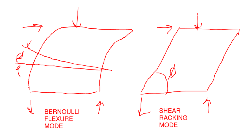
Here's how I believe this works from a theoretical perspective, with reference to the diagram below:

1) The load response -- in the sense of the work that the external shear load performs -- gets divided up into a Bernoulli flexural contribution and a shear racking contribution. Both modes contribute to chord forces with the sum being unaltered by the amount of work done by each mechanism. The sum is a function of equilibrium. The distribution, however, is not.

2) For most things, the Bernoulli flexural load path dominates the stiffness of the system. In such cases, it is reasonable to ignore the shear racking mode entirely.

3) For a squat, multi-panel shear wall, the situation is different and shear racking plays a role that varies between significant and dominant.

4) The chords of the Bernoulli flexural mode will "feel" an intermediate load. The chords of the shear racking mechanism will not "feel" and intermediate load. Consequently, the more load response that is attributed to the the shear racking mechanism:

a) the less an intermediate load will increase compression chord forces.

b) the less an intermediate load will decrease tension chord forces.

c) the less an intermediate load will decrease chord hold down forces.

Basically, the more dominant shear racking deformation becomes, the less intermediate wall loads affect the chords.

C01_tcde5l.png
 
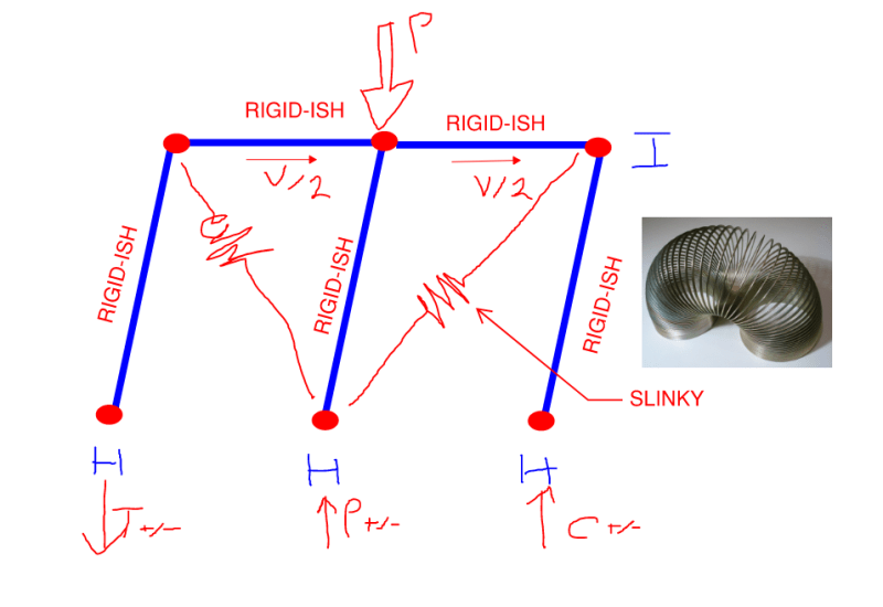
I've long noodled over a discretely braced analog that would:

1) Produce a similar, theoretical effect as I discussed in my last post and;

2) Speak to one's intuition more directly.

For now, the model shown below is the best that I can do. I feel that we could all agree that:

a) The "chords" of this thing will not feel "P" appreciably and;

b) The "chords" would still feel "T" & "C" in the conventionally envisioned manner.

This, again, because this is a deliberately "shear flexible" system by way of the slinkys.

C01_pv3saw.png
 
The theories and research discussed above are fine and dandy, but one must be reasonable as well. If dead load never helps with overturning, then even a super long shear wall will require a holddown at each end. I, for one, don't think that is necessary.

DaveAtkins
 
To maintain the simplified and conservative design approach of a plywood shearwall.....

The wall needs to be considered as rigid and having a pivot point about the edge of compression member.

If after considering the dead weight, the wall end uplifts... then you have to consider the wall as pivoting about the compression member. Theoretically then, due to slip etc, the wall is slightly uplifted... ie it comes up off the concrete. You cannot count on the flexibility of the wall, such that the sill plate would not come up off the concrete with the wall studs, following the assumed rigid plywood action of rocking.

And the sill plate cannot support any weight from the typical stud framing if its off the ground.

But sure, if you want to consider the wall as flexible in the way youve described.. such that each stud transmits load to the sill plate... and the sill plate either supports the stud point load by bending or direct compression...... and the sill deflects in an s shape....... then you must consider every aspect of that assumption. You must consider where the sill plate splices are...... and the effect of anchor bolts....etc.

You cannot pick and choose between design assumptions and "reality" wherever it benefits you. Go with tried and true... and dont think youre smarter than the vast wealth of knowledge that has led to current design approaches.
 
JLSE - never said I was smarter - just asking an honest question and looking for well thought out answers. Seems here there is enough discussion to provoke the thought that just because something is "tried and true" doesn't mean it is accurate or complete. The whole point of research is to see if there is another way. Definitely appreciate the vast wealth of knowledge that has led to the current design approaches, but that doesn't mean we're done exploring those design approaches further.

Appreciate everyone's comments on this thread. Definitely got more participation and discussion than I was originally going for.
 
Status
Not open for further replies.

Part and Inventory Search

Sponsor