Continue to Site

Eng-Tips is the largest engineering community on the Internet

Intelligent Work Forums for Engineering Professionals

  • Congratulations SSS148 on being selected by the Eng-Tips community for having the most helpful posts in the forums last week. Way to Go!

Wood Shear Wall with "Continuous" Holdowns

Status
Not open for further replies.

smokiibear

Structural
Sep 19, 2006
158
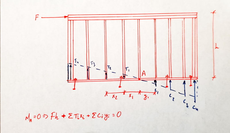
We've got a shear wall with holdowns that are not adequate. Without removing the footing or adding new footing, we thought of trying to holdown the entire wall via every stud or every other stud. Have anyone done this before? Could you advise on the math. I've been at this for while, but not setting up the problem correctly.

Thank you,
 
Replies continue below

Recommended for you

That is essentially how the prescriptive braced walls in the IRC handles it. But if you're doing engineered shear walls with a discreet load path, what you're suggesting is much harder to do. I'm not aware of any "approved" procedures to do it. I suppose you could look at it with an elastic, triangular stress distribution with compression on one side and tension in each anchor on the other. Your highest tension load would be at the end of the wall down to a minimum near where your distribution crosses over zero. But you'd need to be sure of your blocking and panel fastening and everything else to make sure each individual tension load gets distributed up into the wall. For a single family house I might be tempted to try it if there's enough redundancy in the overall design, but for anything really consequential in terms of number of occupants I wouldn't.
 
You could use force transfer around openings which will allow you to potentially use wider piers (FTOA only works at window openings) which will lower your uplift.

No you can't just add holdowns the length of the wall I think that would just be a zipper of holdowns.

Try posting drawings to get a better response.
 
Not entirely sure what you're doing there. Looks like you're trying to use the original tension load and then balance it simultaneously with all of the hold downs and each hold down individually. Which would explain why it doesn't work.

If you must go down this route - to clarify my statement earlier, I'd probably only do it if the house either works with braced walls or we're doing shear walls for something in another part of the house, etc. If it HAS to be a shear wall...I wouldn't. (For instance, if the house has a great room with 20' ceilings and we have to shear walls, but this is in a part of the house that doesn't share a wall line with that and is otherwise compliant with braced wall provisions, I'd be okay justifying it. But if this IS the great room, or the wall is otherwise influenced by geometry or loading outside the scope of braced walls, stick to traditional shear wall design principles and make them fix the footing and hold down.)

Start with a couple of assumptions.
1) You'll have a symmetrical distribution with an infinitely stiff wall and anchors of equal stiffness.
2) Set your maximum compression load in the end studs equal to the crushing capacity of the stud to plate. Make sure each successive compression stud doesn't exceed this either (end stud is usually a double or triple, so it's possible the adjacent single could be overloaded). This would be your capacity check for the wall to determine the maximum moment it can resist. For smaller loads, the distribution would remain the same but the stresses would be lower. So long as the stud layout is symetrical, this means that the tension in each tension stud would conveniently match the compression stud. It might not in practice, but it would be nice. You can always work out the distribution for the actual geometry.
3) Don't rely on the sheathing for stud to plate tension transfer. Provide a discreet connection here.
4) Make sure that your anchors can handle both the shear transfer from plate to foundation as well as the tension transfer.

2021_08_09_6_09_PM_Office_Lens_dluwi4.jpg


(Pretty sure I flipped some arrows there...sorry...)
 
Harbringer said:
No you can't just add holdowns the length of the wall I think that would just be a zipper of holdowns.

Is that really what the test data shows? I don't think it is. I think our design procedures (which assume the full moment is resisted by end posts and / or hold downs) is a conservative assumption adopted by the industry.

However, I believe a method similar to what phamENG spells out is theoretically valid as far as statics is considered. As such, I imagine that the test data will bear this out. However, I also imagine that it's less efficient in terms of cost vs resistance.

The most practical solution might be using FTAO as Harbringer suggested.
 
I don't think this works unless you account for the deflection of the holdowns.

Imho, whatever you come up with for this is not likely to reflect reality. That's why no one does it.
 
I was taking the entire wall to be in tension, except where the load is zero at the end, where compression is, as if it was rotating about the end post. That's not how you would see it?
 
smokiibear said:
I was taking the entire wall to be in tension, except where the load is zero at the end, where compression is, as if it was rotating about the end post. That's not how you would see it?

Nope. I think it's an over simplification and doesn't meet code...at least the code we design for where I live.

The load to the holdowns is not just proportional to the distance from the point of rotation. This would only be true if the wall was completely rigid (its not) and the holdowns did not deflect (they do).

If this was how a wall (with holdowns only at each end) performed wouldn't all of your sill bolts fail in tension during a design event as they would be taking an equal distribution of tension?

I would look to more traditional methods of reducing uplift instead of trying to make the math work out for something that I think could only really be validated by testing.

How much uplift are you dealing with?
 
As I said, what you are proposing is essentially a prescriptive braced wall panel. Essentially every tract home ever built uses this principle and has no hold downs anywhere in the building. So testing has been done. Putting our hands on it may be tough. Here's one article I've found that summarizes tests of a variety of braced wall assemblies, among them a continuously sheathed 22' long panel.
 
Harbringer said:
I don't think this works unless you account for the deflection of the holdowns.

Good point. Though this would depend greatly on the type of hold down.

That being said, I wonder what the test data actually shows. Certainly, we've seen that FTAO works fine. There is also data (I believe) that shows that FTAO also works for door openings and such.... provided you have hold downs at the door openings.

One of my friends did her PhD as part of the CURREE (sp?) wall testing. I should find her contact info and ask her what she thinks. My impression was that if the walls were NOT tall and slender, but more short and squat that they did behave fairly rigidly. And, that hold down deformation was not as much of a factor.

 
My walls have about 10000pounds on walls 8' high and 8' long. Yes...they are basement walls for 17' high clear story walls above :)
 
10kips on an 8' long wall? Don't try to rationalize that. Do it right. You have nearly 10x the loading recommended by the articles I posted above for doing it the way you're proposing.
 
Normally, overturning of a shear wall is considered to be resisted by tension at one end and compression at the other. If the lateral force can be reversed, hold downs are required at both ends. The hold downs must be capable of resisting the tension, and the wall must be capable of resisting the shear in order for the system to work.

If a hold down is provided at every stud, or every second stud, I think it could work, but the lever arm is reduced, so more hold downs would be needed. It would be better to concentrate the hold downs near the end of the wall to improve efficiency.

BA
 
Is your footing adequate for the uplift? If so, can a new anchor rod be installed through the footing and bolted to the bottom?
 
@pvchabot

I thought of that, but our situation doesn't allow on both sides of the wall.

I think we are going to need to have the footings removed and replaced. Was searching for a way out.

Just a tough situation caused by the contractor.
 
I have seen a solution for a grouted anchor for a 4-story tiedown. The contractor missed a tiedown and the foundation designer directed them to core a hole in the slab and grout the new anchor in. 51 kip in tension. The solution was stamped and submitted to the building department. Their assertion was that the properly installed grout had sufficient bond capacity to develop the shear strength of the concrete. I wasn't completely convinced but according to the datasheet he was right. I was reviewing it for the EOR and since the foundation designer was responsible for it and we couldn't find a definitive reason with which to argue, we didn't stand in their way. However, if you don't have sufficient edge distance this may not help.
 
Status
Not open for further replies.

Part and Inventory Search

Sponsor