Eng-Tips is the largest engineering community on the Internet

Intelligent Work Forums for Engineering Professionals

Wood Tie Retaining Wall 2

Status
Not open for further replies.

jerseyshore

Structural
May 14, 2015
702
0
16
US
I haven't seen a new wood tie wall (formerly known as a railroad tie wall) in at least ten years, but just got the possible request to design one out of 6x6's.

I believe the last time my office designed one I was an intern and we used a full crib-style layout (deadmen were continuous for the full length of the wall). I'm pretty sure it was designed as a gravity/MSE wall using the weight of all of the soil area "inside" each crib made up of the deadmen and tiebacks.

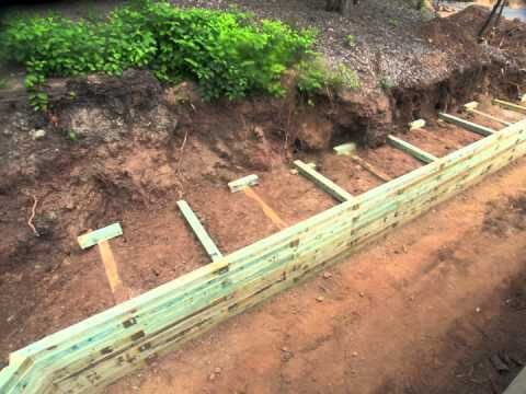
I know most RR tie walls are not designed or built like that. Most have shorter deadmen staggered with tiebacks in alternating courses (see example photo below). Much less digging required this way.

So my question is does anyone have any resources or methods to design these things? Does that gravity/ MSE method even work if it was a full crib?

350fae9dd941c445a67f1284a5620981_fgrc5g.jpg
 
Replies continue below

Recommended for you

I do not know of any resources, but hopefully others have. I'm interested to hear too.

After looking at your sample photo, I did just think of one question. Doesn't it look like the deadmen would still be in the active zone?
 
Certainly not a 'forever' wall, but they can last a good while if done right. Coating the backside with an asphalt based paint would help to keep water from soaking in, and then porous fill, and drain piping (maybe even weeps) will help keep the backside dry-ish. Filter fabric wouldn't really work with all those tie backs, but you might be able to do something between them? Ensuring adequate treatment and/or species selection is also important. I wouldn't build these with stuff from the big box stores. A specialty lumber yard with freshwater immersion rated stuff would be better. Some areas have better luck than others with these. I wouldn't try on that big down here in the swamp, but on a dune or in the hills/mountains...maybe.

The range of recommendations in those prescriptive guides are interesting. Fairfax doesn't even define a max height for wood, but I'd assume it's 4' since that's what the VRC limits non-engineered, residential retaining walls to (and the tie backs are only 6' long). I also think St. Louis has a typo with their 16' height in the elevation view.

 
You're right, not gravity, MSE wall. I will fix my post,

I wasn't 'correcting' you, since it technically isn't really an MSE wall, either; just letting you know you can use the same approach for sliding, bearing and overturning of the bin/crib wall as you would for an MSE. From an external stability standpoint, the analysis for a gravity wall, an MSE wall, or a crib/bin wall are very similar. The internal/structural design is what's different.
 
I have built several of these in my pre-engineer days. Mostly in areas with heavy railway industry and plenty of old ties that can be used on the cheap. We used prescriptive designs similar to the ones you posted.

I have never tried to run any numbers on them, but I would think many of the mechanics of more traditional MSE wall designs would apply (segmental masonry, etc.). I wonder if geogrid tieback could be used in lieu of or along with the deadmen to get a more reliable (and more definable) design.

I agree with the 20 year or so design life. That being said, as long as that is understood, there is definitely a time and place for these type structures.
 
If you drive around any neighborhood in NJ you can find these walls. Super popular in the 90s and earlier. From 3 ft to 10 ft to multiple tall tiers stepped back.

I think most contractors built them somewhat prescriptively as well. And 20 - 30 years is a pretty typical lifespan.

I've never seen a true calculation from a non-crib style wall. It's more of, okay this wall is going to be taller than the last one, let's put the deadmen another foot back.
 
Jersey, these walls are extremely popular in my area in the southeast USA. There is no documented design methodology for designing them that I have been able to find. I occasionally get requests to design them, and I explain that there is no documented engineered design methodology for such walls, so if they are over 4 feet high and an engineered design is required by the AHJ, then another structural system should be used instead.

The full crib design is a legitimate alternative, and there are design references available for full crib designs. Full crib designs work as gravity retaining walls. If you look at the details, I don't think a full crib wall requires any extra excavation and really doesn't require much more timber materials either. However, the full crib design references I have seen require gravel fill, not native soils, so that would be an extra expense both for the gravel fill and for disposing of the native soils.

Another alternative for which you can find engineered design references is a timber pile and lagging style wall.
 
Okay, I'm glad I'm not the only one who has never seen a documented design for these. Which is wild because they are all over the east coast in various heights applications.

Is there anything else like this in structural engineering that's so widely used, but basically never designed?


There are calcs for houses though. Most stuff is prescriptive, but relatively easy to calculate if needed.

As evidenced in this thread so far, no one has ever seen an actual calculation for a RR tie wall with the deadmen, yet they are (were) super popular.
 
I've seen recent drawings for a building in an underdeveloped country, and oh boy, that shit would never pass here. And when it was built, those horrendous drawings weren't even followed. So I think most buildings around the world aren't designed. And almost all of my city was prescriptively designed until like 3 decades ago, with wild inconsistencies in things like using a footing or not. In terms of stuff by "real" engineers, discontinuities in wood diaphragms comes to mind as the #1 thing that everybody knows about but kind of ignores.

The other thing is maybe surcharge of footings. We use 1:1 to 1:2 influence lines for not undermining existing footings. Everybody around here seems to ignore slope stability, whereas it should be done using those trial semicircles and Boussinesq equations or something similar. The catch is that if you did all that stuff, 90% of the designs wouldn't work and you simply wouldn't be able to do things like excavations near adjacent buildings. Not to mention that removing overburden reduces bearing capacity, yet people dig next to existing foundations all the time.
 
It was mostly a joke, but not entirely. For most houses, there's not a single calc done, at least not directly. Most houses don't need an engineer...most of these walls don't need one, either.

But I'd bet these walls could be proven. I'm not volunteering (way to much else to do), but it seems pretty easy if a little complicated. The load paths may be a chore to follow, but not impossible. You need to come at it a little differently then you might approach a normal retaining wall - kind of like designing a masonry wall to span horizontally between buttresses rather than vertically from footing to diaphragm. Your tie backs are your buttresses here. Once you have a reaction, you can look at them and check the passive resistance of the soil that the deadmen are bearing against. Not saying they'd work for large loads or particularly tall heights, but I'm sure they'd work.

 
I've never designed one of these wooden bulkhead walls, but I have seen them up to 15' in height. What is the tieback connection to the wood timbers? Surely there is a big spike connected at each intersection sized for the tieback load. This can definitely be analyzed with a few simple calcs to confirm the concept if you are concerned about blindly following a prescriptive county design. I would not seal designs that I have not vetted myself.

Let us know what you come up with @jerseyshore -- thanks for the post.

"Engineers only know about 80% of the truth, the next 10% is very difficult to achieve, and the last 10% impossible. If we are bound to be wrong, we may as well be wrong simply and conservatively."
 
80percent, there is no standard and there is never an engineered design or a set of construction drawings that specifies the tieback connection to the face of the wall or any other detail. Therefore, who knows what you might get? These are usually built by unskilled landscaping crews at best. The particular connection that you mention (tieback to face of wall) might be one or two spikes of random size or more likely one or two timberlock screws of random size.
 
Status
Not open for further replies.
Back
Top