Continue to Site

Eng-Tips is the largest engineering community on the Internet

Intelligent Work Forums for Engineering Professionals

  • Congratulations KootK on being selected by the Eng-Tips community for having the most helpful posts in the forums last week. Way to Go!

Wooden floor beam

Status
Not open for further replies.

BAGW

Structural
Jul 15, 2015
388
Hi,

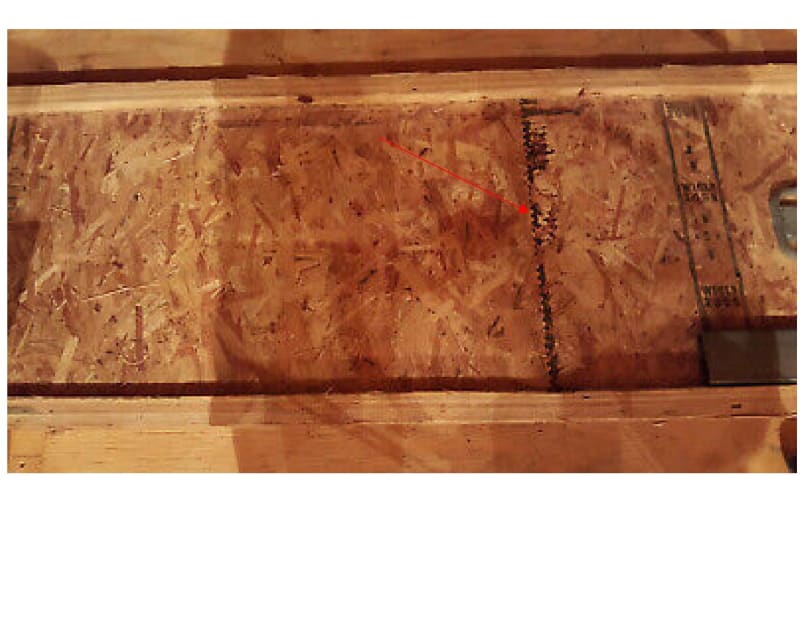
I was looking at some wooden beams for redoing the floor online. I see this crack sort of thing in all the beams supporting the floor. what are those? That cannot be the crack in the beams due to beam overstress. I see that on all beams. Trying to understand what those are.

when I shop for new beams, I see that in the new beams as well. Is it to accommodate thermal expansion?

Thanks
Document1_gjzkzb.jpg
 
Replies continue below

Recommended for you

Are you sure it's not ink from the roller when they proofmark the I-Joists?
 
Ink is on the other side.. if you look at the right side you will see the ink
 
The core of the I-joist is likely constructed of finite length pieces of OSB.
I believe it is a splice. LVL's have those as well.
 
If it’s splice how are the web connected? The flanges are continuous though
 
Looks like there are stitches along the line, I wonder what is that?
 
A stitch joint. Common in manufactured timber. More economical to assemble from smaller pieces.
 
R13 said:
Looks like there are stitches along the line, I wonder what is that?

To provide shear key at the spliced layer.
 
How they stitch it, use wood stapler? Does looks like though.
 
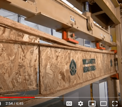
The web splice in the OP photograph looks like a finger joint. The following video shows how I-joists are fabricated in one plant. Webs are made of OSB board. The web splice appears to be a glued butt joint. It passes the strength test(minute 2:45 of the video), but failure occurs at the splice location.


BA
 
The guy call it finger joint, but looks like just straight pieces glued together. Somewhat differ from the OP's photo.

image_nuhzuu.png
 
Indeed, r13, which is why I described it as a "glued butt joint". I believe the "finger joint" or "stitch joint" is probably much better. Failure should not be at the splice.

BA
 
r13,

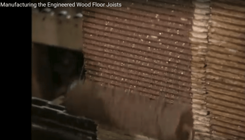
I took another look at the video. Apparently, all four sides of each web panel are run through a profiler, giving them a saw-tooth appearance (see minute 1:20 in the video). So, the ends are not butt joints as I stated above. Perhaps it is too much to expect that failure will not occur at the splice.

image_nr6uz9.png


BA
 
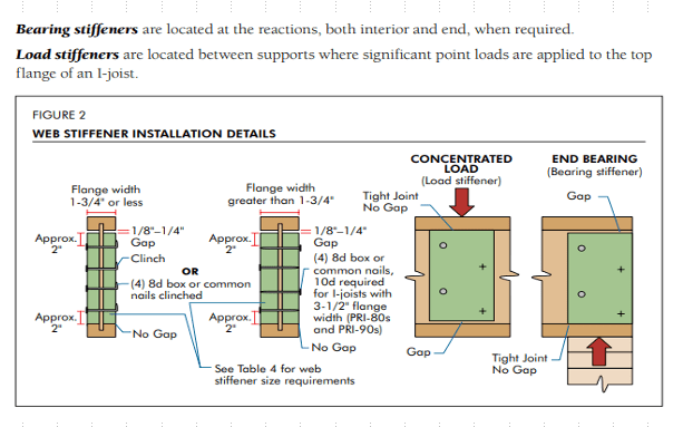
The teeth is too fine to remain contact while the beam deflected, but an improvement from butt joint. I am surprised that there is a lack of literature on the OSB web joint, but I do find details for web strengthening at concentrate load, and the fact that shear deflection is need to be considered in the deflection calculation.

image_haszy2.png
 
If you're unhappy with failure occurring at a glued splice you probably shouldn't use engineered lumber!
 
Tomfh,

For load within the rated capacity, I don't think the web failure mode will ever occur. However, will the capacity increases due to better web connection, or it is something just not worth the escalate manufacturing cost?
 
Yes it’s a matter of economy. It’s cheap to profile the ends and stick them together, however it’s not necessarily what you’d do to ensure a connection that exceeds member capacity, which I thought was what you and BA were arguing for.
 
There are certainly some engineered wood products for which the capacity of the finger jointed adhesive splices are made to exceed the capacity of the same material without the the finger jointed splices.
i.e. a jointed flange/lamination is no weaker than an unjointed one for axial. I'm not sure if I-joist webs are one of those.
 
Status
Not open for further replies.

Part and Inventory Search

Sponsor