Continue to Site

Eng-Tips is the largest engineering community on the Internet

Intelligent Work Forums for Engineering Professionals

  • Congratulations KootK on being selected by the Eng-Tips community for having the most helpful posts in the forums last week. Way to Go!

Woodframe - DL Engaged for Overturning Resisting Moment

Status
Not open for further replies.

Mohzus

Civil/Environmental
May 1, 2015
12
Hi everyone,
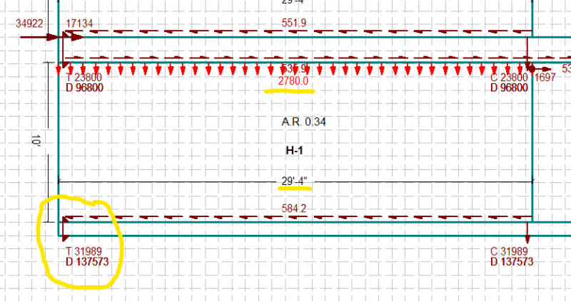
When determining the holdown forces at the ends of a wood shearwall segment, let's say a 29.5' long segment (example below), does the entire dead load applied resist the overturning forces?

Or could only a portion of dead load applied to the wall be considered if the stud shearwall is not rigid enough to drive the dead load out to the ends - for example 5' from the edge on each side of the wall that would contribute. Which would be the proper approach?

Thanks in advanced.
wall_wcskbp.png
 
Replies continue below

Recommended for you

While it seems present in a real situation, the crux is most of the shear wall tests didn't apply a dead load, and it doesn't seem to influence the wall much even when it's there.


Longer walls, of course, would potentially be more flexible between the holddowns as that little snippet mentions. Longer walls should have lower forces at the holdowns as well due to their length. It would be interesting to see how long the shear walls were in these tests, as well, but I've not seen a summary that springs to mind. Maybe somebody else knows of one.

Regards,
Brian
 
I don't consider the global gravity load of a shear wall for overturning resistance because I'm not convinced that it can act rigidly. It's more like a flexible diaphragm than say, a concrete retaining wall or concrete shear wall.

There might be rare cases where you have a beam sitting on an end post, which would be a reliable way to add downward load.

Anyway, some of it seems like engineering judgment to me. I agree with lexpartie's snippet. It has some good stuff in there, especially this golden nugget:

Ultimately it’s up to the Structural Engineer of Record to decide whether or not dead load is included as resisting shear wall overturning.

I don't think I can easily justify with calculations about how rigid a shear wall is and how much of it will contribute to DL resistance. Like you said, maybe take 5' and call it a day. If it's a bearing wall taking dead load (i.e. shear wall perpendicular to joists), it might make sense to incorporate some of it into uplift resistance. I usually ignore it. When I have a gigantic uplift like what you have, I try to find other ways to solve it, like by adding shear walls in other places and using FTAO. I've done buildings over podiums and I can't recall any instance when I had as big of an uplift as what you have there; it would need two Simpson HDU18's or whatever it's called plus a ratcheting take-up device. The buildings are usually set up architecturally to have lots of shear walls so that's how I keep the loading down.
 
Thanks Lexpatrie and Milkshakelake for the help, I agree that taking the entire wall's uplift resistance is a bit of a stretch.

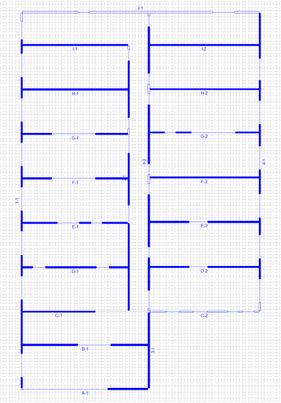
So to bring further context and comment on the gigantic uplift, the structure is a 6-storey woodframe (no podium) and the wall previously mentioned is along shearline H.

Do the uplifts seem out of the ordinary? We do have quite a few walls going E-W. I can share more details if needed.

Also to your point about FTAO, how do you model this with multi segments and/or in woodworks or another program?

123_nv0mzh.png
 
32k seems like an f-ton of tension to manage. How are you planning on tying that down?
 
You can't really model FTAO stiffness in Woodworks. I just approximate it by changing the length of the shear wall, which is admittedly not a great way to do it. I get the deflection at the top of an FTAO shear wall compared to other ones using deflection equations and adjust the model, but it's very fudged. If you want to do it the real way, it would have to be hand calcs. Terry Malone's The Analysis of Irregular Shaped Structures Diaphragms and Shear Walls is a tough read, but it will point you in the right direction. Or be like me and do a silly approximate analysis. I would definitely be using FTAO when you have an uplift that high.

By the way, I don't see taking 5' helping that much. 5' X 20' span X 20 psf DL X 0.6 = 1200 lb per floor. 5 floors x 1200 = 6000 lbs. 32,000 uplift - 6000 = 26,000 lb uplift, which is still massive and will need two very heavy hold-downs. But it does help.

I'm not convinced that putting two hold-downs into one post is a great idea. They are designed for one side with their connections. When connecting from two sides with heavy screws or bolts, how would you know that you're getting twice the capacity? If you can find a hold-down that can handle the 26,000 lbs, I'd use a single one. Edit: Or at least check the manufacturer's notes if it can be done

Also, you could just use flexible diaphragm assumption for this building. That will attract less load to the very long walls.
 
Is that an ASD level uplift force? With that many shear walls, even at 6 floors 32k seems like too much. 19.2k feels a bit more like it....
 
In reality on H line you have H1 and H2 which are segmented shear walls, not a candidate for an FTAO shear wall, and you need a collector across the corridor to force both walls to work together to resist the diaphragm load. For the holdowns you likely would need a pair of 4x8 that will give you enough space for the anchorage into the concrete to not overlap. That will also stay in the "as tested" for the holdown.

Six stories with wood is a computational mess. You should also make it clear that this area should not have any cold joints in the foundation, and your strip footing should be given attention as well for reverse moment (tension) on the top side.


Regards,
Brian
 
I agree, I meant to make other walls FTAO so they attract more load if OP is using rigid diaphragm assumption.
 
Thanks everyone,

To reply each comment:

@XR250 - Indeed, it is a large load and is mostly derived from the location of the building. It's located in high seismic zone with a base shear of 232 kips. The plan would be to use an ATS rod system to deal with the uplift and storey drift/displacement.

@milkshakelake - Thanks for sharing your process. FTAO is something I've been meaning to look more into as these loads get to be over the top when analyzing shearwalls as piers. I've seen that book mentioned here before as well, sounds like it's common reference material, I'll have to pick it up.

And to your comment regarding two holdowns, we are looking at the ATS rod system and I was curious about how much DL engagement I could consider in combination.

Agreed, flexible can work, but there are some other consideration with torsional sensitivity/rigid diaphragm that are being worked out with the south end of the buildings layout.

@phamENG - Thanks for the comment. It's using limit states design, working within Canada.

@lexpatrie - Good advice, appreciate it. That's correct, there is a collector that will run across the corridor to the other shearwall segment. Ah yes, I've seen this paper from woodworks, I'll have another read through it to see if they came up with anything.

 
I'm not very familiar with the ATS system but a 1" diameter rod with ratcheting take-up device should be able to take quite a bit of tension, and also develop enough anchorage development to make it work. I specified ATS system on a wood-over-podium project and contractor wanted to change it because they never used it before. But for something like this, it seems like a necessity. I'd be wary of putting something like a 28 kip load on a double top plate. Not saying there's anything wrong with it, but it deserves some attention engineering-wise.
 
Okay. Those loads make sense in a limit states design context.

28k from an ATS system would need a plate about 9 inches long depending on wood species. At that length, it would have to be really thick to actually spread the load.
 
Status
Not open for further replies.

Part and Inventory Search

Sponsor