Continue to Site

Eng-Tips is the largest engineering community on the Internet

Intelligent Work Forums for Engineering Professionals

  • Congratulations waross on being selected by the Eng-Tips community for having the most helpful posts in the forums last week. Way to Go!

Worries about Torsion; Framing of a Cantilever Deck

AndBre44

Structural
Sep 13, 2019
26
US
Looking for some thoughts on solving a free body diagram after adding in a few variables. For context, this is a home with a cantilevering deck at the second floor that is then being placed over a full glass wall (minus some small 8" wall cavities for HSS columns for a moment frame), with a deck width of 5ft and about 20ft of a joist span between this framing beam and the interior framing beam picking up the other end (essentially making a condition of a beam overhanging a support). The span is about 32ft in length, and requires a W21 to account for required deflection (L/720 because it is holding/over a glazing system).

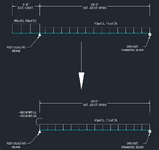
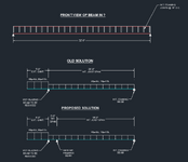
The architect came back saying they would prefer to find a way to match the same depth as the 12" framing across the floor, so I'm attempting to put in some additional framing at the floor level to reduce the size of the steel at this area. I've attached some FBD of the original placement I was using with the overhanging support, and what I'm hoping to attempt now with the new layout; effectively adding a new support to pick up the interior framing load and limit the load on the glazing beam. My main roadblock with this, is that before with the old FBD I understood how the forces fully resolved: A steel outrigger picks up the exterior deck load, its welded to the glazing beam via a shear & moment connection, and then the interior framing joist at the 20ft span effectively supplies the transfer of uplift to the interior framing beam and stops the entire system from rotating.

The addition of that second beam, while it technically does its job of reducing the load put onto the beam from the interior load about 25% (after modeling the connection of the 18ft joist as purely simple), it also effectively removes that lengthy interior span that was going to easily & more directly counteract the cantilever action (The new interior beam can't be put anywhere else along the framing span; the rest of the 18ft of space is all open floor plan). In that same vein, thinking about it in a 3D view makes it hard for me to not picture the torsion that would result in both beams in this way with how the supports affect the deflected shape. Additionally, the reduction in load at the glazing beam likely wouldn't have enough of a reduction to downsize much, maybe to a W18 or a 16 if I use a much heavier one.
Screenshot (228).png

Don't suppose anyone has any thoughts/notices if I'm missing something? If I just need to go back to the client and say they need to drop the expected glazing height/shorten the span I'm welcome to, but trying to see if someone else has a simpler solution to what I'm trying to come up with (or if I'm just overthinking my conditions here).
 
Last edited:
Replies continue below

Recommended for you

Is there a way to reduce the span of the W21 beam to be less than 32 ft? If not, you could use a shallower and heavier section with a similar moment of inertia.

Does the architect realize that the floor joists will have to be on top of the W21 beam (or whatever you reduce it to)? They can't cantilever through the W21 beam.

You should not put that second beam 2 ft from the W21. Your moment and shear diagrams will be all wonky. Your best bet would be to decrease the 20' interior span down to 15 ft or so (you can play around with that number to avoid uplift on the back end of the joists).

Regarding torsion, the support beams won't have any torsion on them because they are pinned supports. How can a torsional load be transferred into these beams by a joist sitting on top of it?

Even if torsional load could be transferred into the support beams somehow, the torsional load would be negligible because the floor joists are bracing the support beam in torsion and the floor joists are much stiffer in regular bending than the support beam is in torsion, so the load would stay with the floor joists and next to no torsional load would be transferred to the support beams.
 
Is there a way to reduce the span of the W21 beam to be less than 32 ft? If not, you could use a shallower and heavier section with a similar moment of inertia.
For lack of better word not without it being impractical; plus as the W section gets heavier the increase in material thicknesses only saves maybe an inch and a half for a massive difference in weight/material cost
Does the architect realize that the floor joists will have to be on top of the W21 beam (or whatever you reduce it to)? They can't cantilever through the W21 beam.
I did bring up that this would be the ideal scenario, but they don't want to lose the height in their window system (its basically the full height of the floor). So for the framing, I was originally planning on using a joist hanger for the interior span and then have a moment connected steel outrigger on the end that was cantilevered; since the joist would just be used as effectively a means of uplift connection I was just planning on having the hanger designed to meet the uplift capacity at the right most interior beam
You should not put that second beam 2 ft from the W21. Your moment and shear diagrams will be all wonky. Your best bet would be to decrease the 20' interior span down to 15 ft or so (you can play around with that number to avoid uplift on the back end of the joists).
That's what I figured, seems like nothing in a configuration like that was going to solve the problem even remotely; so if nothing else I was going to likely just make it a 7ft cantilever (and effectively just check the deflection at the current W21's position to make sure it stays within the expected L/720). The 20ft interior span can't be altered as its open floor area anywhere within that 20' span.
Regarding torsion, the support beams won't have any torsion on them because they are pinned supports. How can a torsional load be transferred into these beams by a joist sitting on top of it?

Even if torsional load could be transferred into the support beams somehow, the torsional load would be negligible because the floor joists are bracing the support beam in torsion and the floor joists are much stiffer in regular bending than the support beam is in torsion, so the load would stay with the floor joists and next to no torsional load would be transferred to the support beams.
This is probably more clear in terms of question based on my point about using a joist hanger & steel outrigger, that's where my thought of torsion was coming in. That said, I can see what you're describing in the second portion and I can see how that's the case; I think my brain never went to thinking of the bending strength of the joists vs. the torsion that actually gets applied to my framing beam. I appreciate the insight!
 
A steel outrigger picks up the exterior deck load, its welded to the glazing beam via a shear & moment connection, and then the interior framing joist at the 20ft span effectively supplies the transfer of uplift to the interior framing beam and stops the entire system from rotating.
I don't feel great about that bolded statement. If I understand it correctly, it would imply a moment connection between your interior joists and the steel beam supporting them. And that would be weird / difficult to do.
 
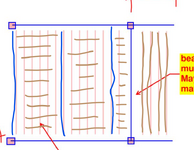
@AndBre44 : this is a permutation of your scheme that I could get behind, at least technically. Under this arrangement I feel that you could assume that the two 32' beams share all loads equally.

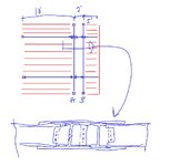
Granted, this is pretty exotic, pretty expensive and, therefore, unlikely to come to pass. That said, maybe this can be your "I can make all your architectural dreams come true if money is no object. If money is an object, I'll take a midspan post please".c01.JPG
 
I had something fairly similar once (not sure it was built, but it got to shop drawings...) I had trusses running left-right and there was a pocket for the steel beam that runs in-out of the page. Nobody said it wouldn't work, but I didn't get to see the project through completely, there were about forty "way too ambitious" architectural details on that project, cantilevers in two directions, "no" floor framing, etc. etc. etc. It did get built, and I probably could have made my life easier with a few "no" answers. Naturally it was "basically a box" to the Architect.... and one whole side of the building was about 100% glass, so there was a monster moment frame on that side, too.

How much of your W21 is from that stringent deflection limit you've set, because maybe there's a way to get around that, either via some camber, some deflection clips or clever detailing ("by other") and a way to tolerate more deflection. Another question I'll put up there is how much of this are you considering unbraced, versus depending completely on the framing above to brace the top flange of the W21. If your deflection limit is really high, I would expect that the braced/unbraced question wouldn't have much influence, so if you start to get into a region where it's not deflection governing the design, then the strength and the unbraced length becomes more of a concern.

The torsion you are concerned with seems to be "redundant torsion" in the context of a concrete beam, if you know that term. If it's like regular wood joists that are the primary system, that would have trouble, in my mind, of transferring a torsion into the steel girder/beam under it.
 
KootK's solution in his sketch seems like the best way to go to keep your structure depth down. It will allow the floor joists to not be above the steel framing and it utilizes two beams to lower the require steel beam depth. There is lots of added cost as he said with the extra steel and complicated field welds. It seems like your best bet assuming price isn't an issue.
 
I don't feel great about that bolded statement. If I understand it correctly, it would imply a moment connection between your interior joists and the steel beam supporting them. And that would be weird / difficult to do.
So in my mental image of this situation, the steel outriggers would have a fully rigid & welded connection to my steel beam, while my framing joists were going to be put on top-mounted joist hangers with an uplift capacity that are welded to the top flange of the steel beam. If I were to use the quick diagram of earlier (i.e. exterior deck is on the left interior span is on the right), my thought process is that when my exterior deck is loaded and causes my beam to begin to rotate (in this case counter-clockwise), the hanger would begin to lift and effectively place an uplift load onto my joists, which would resolve at the back half of the 20ft span as would be expected of the load placed by an overhanging cantilever. So I was under the impression that as long as the uplift capacity of that welded hanger was greater than the moment its resolving at the steel outrigger weld, that this would be an acceptable means of resisting that rotation. This is also not considering the load placed on that 20ft interior span which would also provide uplift resistance.

As someone looking to learn, is there a flaw in my reasoning above? I've seen something similar once before on a residential project and my team leads at the time didn't seem to harbor any objections to it
 
With my solution, you'll probably lose an 1" to the flange plate thicknesses, 1/2" to tolerance, and maybe 1/4" to elevating the lumber 1/4" above the steel for shrinkage. Pretty soon you're out of plenum space for the beans again.
 
@AndBre44 : this is a permutation of your scheme that I could get behind, at least technically. Under this arrangement I feel that you could assume that the two 32' beams share all loads equally.

Granted, this is pretty exotic, pretty expensive and, therefore, unlikely to come to pass. That said, maybe this can be your "I can make all your architectural dreams come true if money is no object. If money is an object, I'll take a midspan post please".View attachment 623
In my own brain storming the rest of the day I was coming to something not too far off from this, effectively just making it one rather large & complicated cross section to act as a single member on its own. I will say the client has been more than open to introducing most steel in the effort of achieving his architectural vision, so it wouldn't surprise me if I explained what it would require and they don't bat much of an eye, but every project has its budget especially for a residence.

I'm almost tempted to not bring it up on the off chance money truly is no object and then I have to go through designing the connection and load transfer of something like this...maybe I just leave it in the section drafted this way and as a "design by others"...
 
I had something fairly similar once (not sure it was built, but it got to shop drawings...) I had trusses running left-right and there was a pocket for the steel beam that runs in-out of the page. Nobody said it wouldn't work, but I didn't get to see the project through completely, there were about forty "way too ambitious" architectural details on that project, cantilevers in two directions, "no" floor framing, etc. etc. etc. It did get built, and I probably could have made my life easier with a few "no" answers. Naturally it was "basically a box" to the Architect.... and one whole side of the building was about 100% glass, so there was a monster moment frame on that side, too.
Very similar here with corner framing decks and a lot of glass, not to mention a full height basement close to the groundwater table and low soil quality; certainly challenging in multiple aspects so far. Less so an architectural "this is too much" as much as an ambitious homeowner with a lot of capital to burn. The only reason the moment frames on this building aren't too excessive is because its only two stories with the basement and there's (barely) just enough solid walls for lateral resistance to only need one wall to be resisted via moment frame (surprise surprise, the same wall in this thread)
How much of your W21 is from that stringent deflection limit you've set, because maybe there's a way to get around that, either via some camber, some deflection clips or clever detailing ("by other") and a way to tolerate more deflection. Another question I'll put up there is how much of this are you considering unbraced, versus depending completely on the framing above to brace the top flange of the W21. If your deflection limit is really high, I would expect that the braced/unbraced question wouldn't have much influence, so if you start to get into a region where it's not deflection governing the design, then the strength and the unbraced length becomes more of a concern.
At the moment since it's over/above glass I'm using a deflection limitation of L/720, and since the span is so high I'm using that as a total load not just live load; I've always had a habit of adding additional stringencies on my total deflection after going in a span > 20ft. I hadn't thought about camber as an option, truth be told as much as I know the term and how it can be a solution for heavy deflection I've just never had a project where the beam span was large enough to warrant it. That could be a potential way to offset it, and then in which case I could understand how the question of unbraced length would come into play.

The torsion you are concerned with seems to be "redundant torsion" in the context of a concrete beam, if you know that term.
I can't say I've heard that phrase before, but given the other responses above I can see what you mean by that term. I think similar to what I said about KootK's schematic, it was hard for me to not see a solution that wasn't just combining the two beams into a single cross section without knowing that these two acting independently would lead to something not staying straight.
If it's like regular wood joists that are the primary system, that would have trouble, in my mind, of transferring a torsion into the steel girder/beam under it.
I just posted the below in terms of KootK's response to a similar line of thinking; would love your own thoughts on my logic as well.
So in my mental image of this situation, the steel outriggers would have a fully rigid & welded connection to my steel beam, while my framing joists were going to be put on top-mounted joist hangers with an uplift capacity that are welded to the top flange of the steel beam. If I were to use the quick diagram of earlier (i.e. exterior deck is on the left interior span is on the right), my thought process is that when my exterior deck is loaded and causes my beam to begin to rotate (in this case counter-clockwise), the hanger would begin to lift and effectively place an uplift load onto my joists, which would resolve at the back half of the 20ft span as would be expected of the load placed by an overhanging cantilever. So I was under the impression that as long as the uplift capacity of that welded hanger was greater than the moment its resolving at the steel outrigger weld, that this would be an acceptable means of resisting that rotation. This is also not considering the load placed on that 20ft interior span which would also provide uplift resistance.

As someone looking to learn, is there a flaw in my reasoning above? I've seen something similar once before on a residential project and my team leads at the time didn't seem to harbor any objections to it
 
AndBre44,
If you are still considering your idea, could you sketch up your section view with the steel outriggers, steel beams and the uplift hangers on the joists? I'm having a hard time picturing what you are describing and figuring out what the FBD would look like.
 
Can I just throw a completely different concept here, what about two girders that overhang at the columns, left-right, and the framing between, up-down? If you needed that moment frame, the steel beam is now non-bearing (except a wall above?), now you need the beam depth to control deflections of the moment frame, but it removes the other constraint (more).

Redundant torsion - to explain a bit, is in the ACI, for example on purlin (edge) beams supporting a slab, if the slab cracks at the top, if there's no rebar to resist that top tension that's bending in slab, then the resulting torsion can't get into the edge beam that's perpendicular to the slab span direction.
 
AndBre44,
If you are still considering your idea, could you sketch up your section view with the steel outriggers, steel beams and the uplift hangers on the joists? I'm having a hard time picturing what you are describing and figuring out what the FBD would look like.
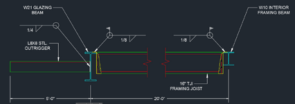
Not a problem at all, here's a better section view of what I was expecting, the loads were provided in the figure in the original post's screenshot:

Screenshot (231).png

The idea would be the all-around web on the outrigger would apply the moment directly to the steel beam, then as the beam begins to rotate as a response it will lift the joist and that uplift will get resolved by the interior framing beam. I'm effectively trying to have the outrigger be one connection resulting in a moment being placed at the "pinned support" that is the W21, and then have that resolved via the uplift of the joist that would be still in the simply supported version of this FBD:

Screenshot (232).png
 
Thanks. I understand your thought better. I don't think it is practical to get that moment to develop in the floor joists.

If you can somehow transfer those moments from the outrigger into the floor joists, you could have uplift at the W10 reaction, so a joist hanger with uplift capacity could be necessary. How are you going to transfer that moment into the joists to begin with? The joist hanger how you have it shown will not transfer any moment.

You could investigate using an HSS instead of a W21 as it is better in torsion. You could also consider replacing every 4th or 5th joist with a W16 (matches joist depth) that would have a moment connection into the W21. This would effectively transfer the moment out of your support beam. You could determine the necessary spacing of the W16's based on how low the torsional span should be for rotation and stress.

That suggestion does not solve the W21 being too deep though.
 
Thanks. I understand your thought better. I don't think it is practical to get that moment to develop in the floor joists.

If you can somehow transfer those moments from the outrigger into the floor joists, you could have uplift at the W10 reaction, so a joist hanger with uplift capacity could be necessary. How are you going to transfer that moment into the joists to begin with? The joist hanger how you have it shown will not transfer any moment.

The torsional capability of the W21 isn't as much of my concern if only because technically the specified beam is capable of withstanding the torsion, and the joist hanger does have an uplift capacity that would be more than sufficient, but I can understand looking at that its not so much the reactionary concerns at the supports, but more not resolving the moment that's still present physically at the W21 beam, ...seems like I'll have to rethink this anyways.

You could investigate using an HSS instead of a W21 as it is better in torsion. You could also consider replacing every 4th or 5th joist with a W16 (matches joist depth) that would have a moment connection into the W21. This would effectively transfer the moment out of your support beam. You could determine the necessary spacing of the W16's based on how low the torsional span should be for rotation and stress.

That's probably going to be the way forward given what's said above; effectively just have some steel placed at intervals necessary to resist the rotation on the central beam and have that be how the rotational force gets resisted.
That suggestion does not solve the W21 being too deep though.
It doesn't but by now I'm likely going to end up telling them nothing can be done about it; I'm certainly not a wizard and can't make the laws of physics change. At most per your other prior suggestion I'll likely look into if I can get a W16 or W18 with camber to do the trick, unless they want to provide some other means of support for me to use if they're dead set on the lower framing beam height.


Also, seeing as I haven't said it yet till this point, thank you so much for the discourse and for the explanations! You and everyone else that has responded that is.
 
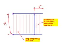
lexpatrie's latest sounds pretty good to me and is something that I've done successfully before. 32' is a long infill span in wood but, so long as you can work that out, I'd think that you'd be off to the races, and at a reasonable price point. This is my interpretation of that. It's simple. And simple is usually good.

c01.JPG
 

Part and Inventory Search

Sponsor

Top