Looking for some thoughts on solving a free body diagram after adding in a few variables. For context, this is a home with a cantilevering deck at the second floor that is then being placed over a full glass wall (minus some small 8" wall cavities for HSS columns for a moment frame), with a deck width of 5ft and about 20ft of a joist span between this framing beam and the interior framing beam picking up the other end (essentially making a condition of a beam overhanging a support). The span is about 32ft in length, and requires a W21 to account for required deflection (L/720 because it is holding/over a glazing system).
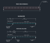
The architect came back saying they would prefer to find a way to match the same depth as the 12" framing across the floor, so I'm attempting to put in some additional framing at the floor level to reduce the size of the steel at this area. I've attached some FBD of the original placement I was using with the overhanging support, and what I'm hoping to attempt now with the new layout; effectively adding a new support to pick up the interior framing load and limit the load on the glazing beam. My main roadblock with this, is that before with the old FBD I understood how the forces fully resolved: A steel outrigger picks up the exterior deck load, its welded to the glazing beam via a shear & moment connection, and then the interior framing joist at the 20ft span effectively supplies the transfer of uplift to the interior framing beam and stops the entire system from rotating.
The addition of that second beam, while it technically does its job of reducing the load put onto the beam from the interior load about 25% (after modeling the connection of the 18ft joist as purely simple), it also effectively removes that lengthy interior span that was going to easily & more directly counteract the cantilever action (The new interior beam can't be put anywhere else along the framing span; the rest of the 18ft of space is all open floor plan). In that same vein, thinking about it in a 3D view makes it hard for me to not picture the torsion that would result in both beams in this way with how the supports affect the deflected shape. Additionally, the reduction in load at the glazing beam likely wouldn't have enough of a reduction to downsize much, maybe to a W18 or a 16 if I use a much heavier one.

Don't suppose anyone has any thoughts/notices if I'm missing something? If I just need to go back to the client and say they need to drop the expected glazing height/shorten the span I'm welcome to, but trying to see if someone else has a simpler solution to what I'm trying to come up with (or if I'm just overthinking my conditions here).
The architect came back saying they would prefer to find a way to match the same depth as the 12" framing across the floor, so I'm attempting to put in some additional framing at the floor level to reduce the size of the steel at this area. I've attached some FBD of the original placement I was using with the overhanging support, and what I'm hoping to attempt now with the new layout; effectively adding a new support to pick up the interior framing load and limit the load on the glazing beam. My main roadblock with this, is that before with the old FBD I understood how the forces fully resolved: A steel outrigger picks up the exterior deck load, its welded to the glazing beam via a shear & moment connection, and then the interior framing joist at the 20ft span effectively supplies the transfer of uplift to the interior framing beam and stops the entire system from rotating.
The addition of that second beam, while it technically does its job of reducing the load put onto the beam from the interior load about 25% (after modeling the connection of the 18ft joist as purely simple), it also effectively removes that lengthy interior span that was going to easily & more directly counteract the cantilever action (The new interior beam can't be put anywhere else along the framing span; the rest of the 18ft of space is all open floor plan). In that same vein, thinking about it in a 3D view makes it hard for me to not picture the torsion that would result in both beams in this way with how the supports affect the deflected shape. Additionally, the reduction in load at the glazing beam likely wouldn't have enough of a reduction to downsize much, maybe to a W18 or a 16 if I use a much heavier one.

Don't suppose anyone has any thoughts/notices if I'm missing something? If I just need to go back to the client and say they need to drop the expected glazing height/shorten the span I'm welcome to, but trying to see if someone else has a simpler solution to what I'm trying to come up with (or if I'm just overthinking my conditions here).
Last edited:
