Continue to Site

Eng-Tips is the largest engineering community on the Internet

Intelligent Work Forums for Engineering Professionals

  • Congratulations waross on being selected by the Eng-Tips community for having the most helpful posts in the forums last week. Way to Go!

WPS joint design 1

Sep 29, 2024
8
IMG_20241024_091818_edit_174176600939047_p1rsrv.jpg
Screenshot_20241024_092309_ndutz1.jpg


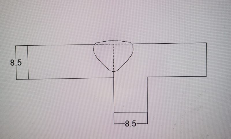
If I have two UPN200 to be welded, like in the photo,
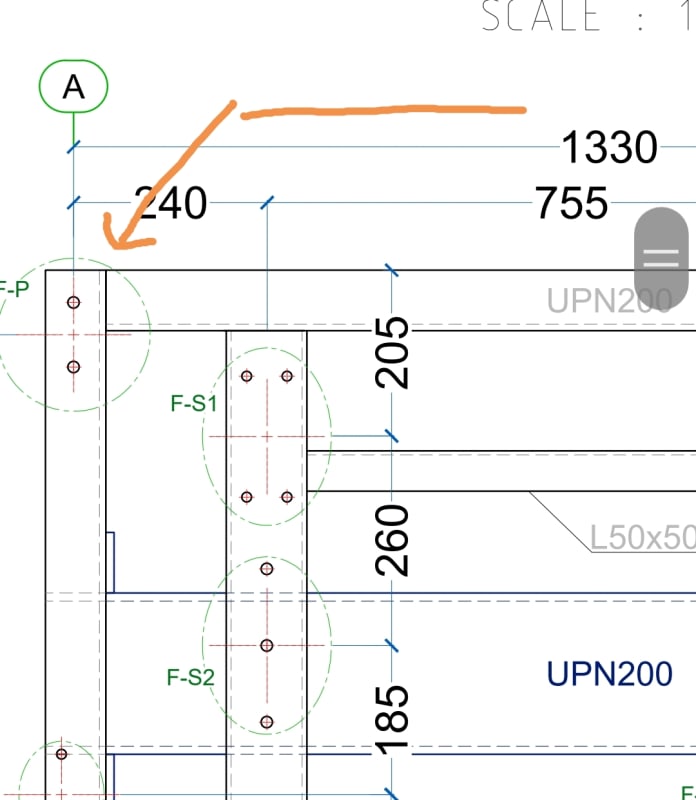
Is it possible to use the weld all-around symbol without seperating each welding joint, can I take the part directly from the drawing, and use two UPN200 in design directly, In WPS according to ASME IX.

Is the joint in other photo, a butt joint or a corner joint?

Thanks
 
Replies continue below

Recommended for you

Sorry, but I'm not sure I understand the question. I have no idea what UPN200 means. Is that a type of base metal? It doesn't appear to specify a shapp because it appears to relate to a structural angle and a structural channel. Are you asking as a designer or as a welder?

As a designer, I would think you would have to know the forces/loads to be transferred from one member to another and then decide what weld type would do the job, i.e., fillet on one side or a groove weld on one side or both sides? Whether a complete joint penetration groove weld is required or whether a partial joint penetration weld is sufficient? If a PJP groove weld is sufficient, what weld size is needed?

As a welder, it isn't your responsibility to design the weld. It is your job to follow the drawing and deposit the welds specified by the drawing.

Best regards - Al
 
Thanks for the clarification.

Best regards - Al
 
General engineering practice is fillet weld on the internal flanges and web.
Fillet weld on the external web.
PJP or CJP (based on loading) on external flanges.
 
THANK YOU all for your help.
It is actually a galva structure(a cabin) used for transporting a 1200L storange tank. About the loads, the mechanical engineer got that covered. It only needs PJP double V fillet welds according to the engineer.

My work is to design and write the preliminary WPS. It is always revised carefully and directed by a mechanical engineer (my boss and mentor at the company) and an IWE (my mentor at the training center).
However, these two have great work loads. And I can't ask them about every detail.

And I thank god that I have this free platform to learn (which is my ultimate goal) where knowledgeable experts share their thoughts. I know that I am under-qualified, but how would I learn if I don't ask questions. (we don't have online courses and I get welding documents through my personal efforts...).
 
Without knowing the loads/forces being transferred from one member to another, how can one size the welds? Another consideration is the design standard and the allowable unit stresses that are permitted. In the case of AISC/AWS, the allowable shear on the base metal is 0.4(YS), allowable tension on the base metal is 0.6(YS). The allowable on the fillet weld is 0.3(Tensile strength of the filler metal), i.e., a fillet weld deposited using E70ksi filler metal is 927#/1/16-inch leg x 1-inch length. Usually, if the base metal has a yield strength of 36 ksi, the limiting factor is the allowable for the base metal. Similar allowable for PJP groove welds, and in the case of a CJP groove weld, the allowable on the weld would be the same as the base metal if matching filler metal is used.

So, it's tough to give you an answer without additional details.
 

Part and Inventory Search

Sponsor