Continue to Site

Eng-Tips is the largest engineering community on the Internet

Intelligent Work Forums for Engineering Professionals

  • Congratulations KootK on being selected by the Eng-Tips community for having the most helpful posts in the forums last week. Way to Go!

Zero Sequence Impedance, medium voltage cable supply

Status
Not open for further replies.

Pdave6

Electrical
Apr 14, 2020
23
thread238-332968
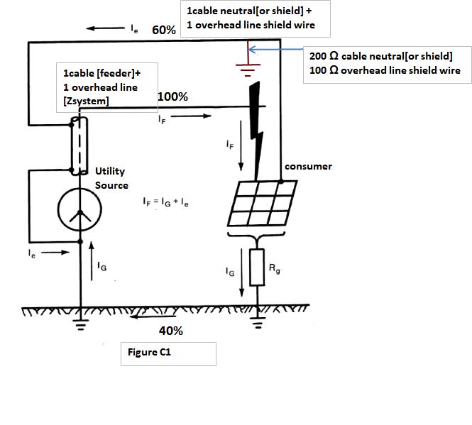
1. I have received positive, negative and zero sequence impedance from the utility for 33 KV feeder, which will supply about 12 MVA to our substation. The measured ground grid resistance is 1 ohm. If I assume a ground fault where 40% of fault current returns thru ground and 60% returns thru shields of 35kV cable, I believe the zero sequence impedance given by utility cannot be used directly in
If = 3*V / (Z1 + Z2 + Z0 + 3*Zn) as the utility has developed a network to have 100% current returned and their Z0 is based on this 100% supply and return. The value of Z0 for 100% supply of fault current and 60% return thru their network will require some new value of Z0.
Unless I have utility's network, I cannot find exact value of new Z0. Is my understanding correct ? Of course, utility will not give that kind of detail information.
2. If the 40% ground fault current flows back thru deep ground to supply substation, the ground grid resistance at our substation will raise the potential at our substation, and will drop the potential at supply substation depending on the resistance of supply station ground grid. This network will be in parallel to the one returning 60% current. Does utility ever give their supply substation resistance, so that one can have total resistance offered to ground current returning to supply station ?
Thanks.

 
Replies continue below

Recommended for you

How did you use the Zo to estimate the split factor S?

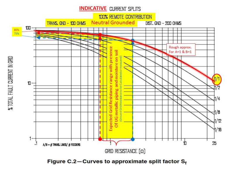
Below is one example of a family curve to determine approx. the split fault factor. Notice that the factor are: grid resistance and No shield or underground secondary feeders.

>>>
Split_Factor_ab3yx1.jpg
 
It is very interesting indeed to attempt to use the C Annex [IEEE 80] curves in order to state the
Figure_C1_IEEE_80_jsaee9.jpg
Sf factor. However each one of this curves consider at least one overhead line. Never the less there are typical overhead line [length, conductors, number of towers, resistances].
If you have a single supply cable and unknown grounding resistances the ABB Switchgear Manual 11edition Table 5-10 recommends for one cable of 20 kV XLPE 95 mm^2[4/0] copper 16mm^2 shield
Sf=0.5-0.6.
 
Thanks Cuky2000.
Thanks 7anoter4. You mentioned Annex C in IEEE 80.....seem very useful reference. I will go thru it. I do not have ABB Switchgear manual, but I see that I can order one for few bucks. As a customer of utility, utility generally, only supply zero sequence impedance at the point of connection, they do not mention their Sf factor. Do I need utility Sf at the point of connection ? My ultimate goal is to find ground potential rise at our 33kV substation.
 
No, utility usually does not provide the Split or Current division Factor S[sub]f[/sub] = I[sub]g[/sub]/I[sub]f[/sub].

The S[sub]f[/sub] is either calculated with the data provided by the utility such as the largest ground-fault current (LG or LLG) and the system sequence impedances including the shield wire zero sequence and the X/R ratio. Modeling the system could be tedious and somehow complex that could be modeled using commercial software or hand calculation.

I am not sure if the above approach can be justified for a simple 33 kV system. An alternate approximate option is to use the graph mentioned earlier that can be available in the IEEE Std 80 Appendix C In many instances.
 
If you can use a standard from IEC World-as BS or ENA Recommendations [it is still free] as
Ena RISE OF EARTH POTENTIAL 2017
ENA Engineering Recommendation EREC S34
Appendix D Formulae for determination of ground return current for earth faults on metal sheathed cables
FIG. D1 is for the ground current calculation for a single supply cable [different types of 33 kV].
 
In my opinion if the utility stated to cancel the shield circulating[returning] current that means the cable is grounded only at your substation [the shield is grounded only in one point so no circulating current is expected] and Zo remains the same [it does not depend on shield impedance but only on earth resistivity, frequency, cable cross section and core distances ].
Zn will be the sum of substation and utility grounding grid resistances.
The short-circuit current will decrease a little since the shield resistance [parallel to ground] is infinite now.
In this case GPR [and touch and step potentials] will rise 100/40=2.5 times [approx.]
 
Thanks cuky2000.
Thanks 7anoter4. The papers you mentioned are very interesting and lot of very useful information. I still have to go thru second paper. I have to discuss about another project I have to start shortly. We will have One 13 kv 3 phase feeder come to the underground compact substation (my guess 40'x30'). We have to overhaul this substation completely, including 13kV incoming feeder. This substation may be 80 to 100 year old which is feeding 625V dc nominal, positive to contact rail (or third rail) to power subway trains running under large street.
1. Earlier many years ago, the theory was to bond all underground steel, to collect negative return leaking current from rails, and connect thru diode to negative bus. Now the steel is still bonded together but not connected to negative bus to avoid corrosion. The ground bus on the periphery wall of substation will be isolated from steel columns of the substation room, as much as possible.
2.The utility, based on years of experience of circulating dc current in the shields near subway system, wants to isolate 13kV cable shield in the first manhole outside substation. We will do single point shield grounding in our substation.
3.This is existing underground facility. Because of above 2 items, the only option left for grounding is 3" water line coming into substation. I believe, because of tonnes of steel underground, this type of structure never required any additional grounding at that time. But now I have only one water line to connect to. I am afraid that this will cause problem with Ground Potential Rise. I still do not have fault current or sequence impedance from utility. We will measure ground resistance after we build peripheral ground and waterline connections. All ground fault current will have to go thru waterline initially and once outside substation, it will be in the ground. Assuming utility shield grounded at manhole which is nearby, some return current will be picked up by 13kV cable shields.
4.The benefit of less corrosion, will result in more GPR. What options are possible to reduce grounding resistance in such situation?
 
7anoter4..The papers you mentioned have tremendous good information. ENA Engineering Recommendation EREC S34.....on page 36 of 81....
For 5 kM of 132 KV solid dielectric cable, table 12 shows that only 0.067x 3I0 current will flow back thru deep earth. Very interesting. Should the last 2 column headings of table 12 be "IE..." instead of "IES/IE..." ?
Thanks.
 

There is a possibility of isolating the cable and other metallic infrastructure under the normal operating conditions and connecting momentarily to the metallic UG structure during a LG or LLG fault scenarios using a surge arrester or surge voltage limiter (SVL).

[sub]A similar application for ground isolation system is described below:

1) HV pipe-type cable with cathodic protection is working successfully for many years in HV substations.
2) We developed a conceptual ground isolation system for an HVDC project for a parallel section to a third-party pipeline.
3) A shield wires circuit for a 500 kV T. Line used to reduce losses in the form of leakage current during normal operation and allow to flashover to ground via a MV insulator with arcing horns a lightning scenario.
[/sub]

 
Thanks cuky2000. You have very good suggestion. I have only water line pipe to connect to inside substation. You are correct that I should look into if I can connect steel building columns to ground during fault thru SVL, to enlarge area of ground current dissipation. If utility will isolate the shield inside substation, rather than in first manhole, I will have a chance to connect shield thru SVL. But utility may have developed their standards over the years, to do things in certain way. I can run ground wire to first manhole, but I believe street manhole will not be good place to install SVL where there is always possibility of water getting in.
 
Hi Odave6.

It is a common practice to install SVL in manholes in a watertight enclosure (link box). Those enclosures are available in none corrosive materials such as stainless steel with bolted gasket.
Cross-Bonding-Link-Box-Underground-type-SVL-IP68-EM.10.04.03.png

Below is an excerpt posted in another discussion in this forum.
Sample_of_Cross_Bonding_Link_Box_qggdig.jpg

 
Status
Not open for further replies.

Part and Inventory Search

Sponsor