Eng-Tips is the largest engineering community on the Internet

Intelligent Work Forums for Engineering Professionals

  • Congratulations waross on being selected by the Eng-Tips community for having the most helpful posts in the forums last week. Way to Go!

joist shoe capacity 1

Status
Not open for further replies.

LOKSTR

Structural
Apr 15, 2005
122
CA
How do we calculate joist seat capacity of an existing steel joist?
The seat in question is 2.5 in deep. The joist configuration is top and bottom chord(1.2 in. depth and 3.5 in wide) is a hat section with pipes(crimped ends)as webs. The end diagonal is a flat bar which is welded to a trapezoidal shape gusset welded to both end diagonal and top chord.
Joist shoe is made up an inverted hat section welded to underside of top chord hat section. Looks like two hat sections as mirror image of each other.

 
Replies continue below

Recommended for you

I looked into this quite extensively in the past: Link. In particular, check out the first sketch that I posted regarding seat mechanics.

This issue frustrated me terribly. Manufactures couldn't seem to tell me how the seats are designed and their printouts didn't list anything other than shoe capacity. I suspect that the shoe capacities may be based on testing but I couldn't get my hands on that either.

There are several joist reinforcement specialists that operate in my market and I managed to get my hands on their calculations. None of them addressed the shoe capacities at all for new, heavy RTU and drift loads. I feel that the joist shoes would be the most vulnerable element under increased load.

I like to debate structural engineering theory -- a lot. If I challenge you on something, know that I'm doing so because I respect your opinion enough to either change it or adopt it.
 
KootK,

Thanks. looks like you were in the same situation as I am now.
How did you calculate joist shoe capacity in your case to carry new loads due to RTU and snow drift?

I am thinking of calculating hat section shoe web shear and web buckling capacity based on CSA S-136 using 2.5 in depth of web for hat section to verify if it can take new support reaction.
Is this approach reasonable?

 
LOKSTR said:
Thanks. looks like you were in the same situation as I am now.

Yes, welcome to hell. I had $1500 to do eight of these and got my ass handed to me.

LOKSTR said:
How did you calculate joist shoe capacity in your case to carry new loads due to RTU and snow drift? I am thinking of calculating hat section shoe web shear and web buckling capacity based on CSA S-136 using 2.5 in depth of web for hat section to verify if it can take new support reaction.

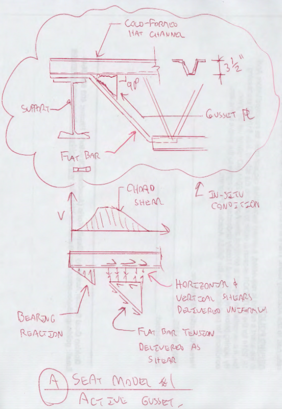
I went with the force transfer model shown below. When I asked the joist supplier about the intent of the triangular wedge thing, they said "not really sure, probably a belt and suspenders / feel good kind of thing". I'm very skeptical of that and have come to believe that the wedge is critical to the design. Here's what I checked:

1) Welds joining last diagonal to wedge.
2) Welds jointing wedge to top chord.
3) Bending of hat section bottom flange spanning between hat section webs.
4) Hat section web shear yielding and shear buckling, yielding, and crippling as you mentioned, accounting for the splay of the webs relative to the applied loads.

I never did feel very confident in my approach. Part of the reason for that is that, according to my assesment, the shoe was woefully under capacity even for the joists original load. KootK no understando.

Capture_jlxtot.png


I like to debate structural engineering theory -- a lot. If I challenge you on something, know that I'm doing so because I respect your opinion enough to either change it or adopt it.
 
Just saw BA's sketch. I'm willing to be a bit more flexible on the importance of the wedge when the last diagonal is a tube as opposed to a flat strap. The tube should be stiffer flexurally and can perhaps distribute load to the supporting welds without initiating an unzipping failure (option 2 in the sketch that I posted in the other thread).

I like to debate structural engineering theory -- a lot. If I challenge you on something, know that I'm doing so because I respect your opinion enough to either change it or adopt it.
 
The page I showed came from the catalog of Great West Steel (GWS) who are no longer in business. They typically used a wedge shaped plate between the end tension diagonal and top chord as seen in the photograph above and as discussed by KootK. I agree that the wedge shaped plate is necessary.

The statics of the joist shoe are not entirely clear, but if the centroid of the end diagonal extended meets the centroid of the top chord at a point inside the bearing surface, I would limit my check to the strength of the end diagonal and the strength of welds to the wedge shaped plate. Those welds should be adequate to transfer 50% of the tensile force in the end diagonal to the top chord.

BA
 
For what it is worth, bar joists are generally "qualified" by testing and so earn their load ratings. In addition, they have to meet other SJI qualifications but our concerns about their strength are primarily arrived at by the proof-testing of their design. Note that their welds do not have to comply with AWS and some of them will make your teeth hurt.
Can you get better info from the Steel Joist Institute? Joist ends must be strength-qualified to meet a variety, or worst case, of the adjacent joist size load capacity.
 
BAretired said:
Those welds should be adequate to transfer 50% of the tensile force in the end diagonal to the top chord.

Assuming two welds, is that 50% in each or 50% total?

I like to debate structural engineering theory -- a lot. If I challenge you on something, know that I'm doing so because I respect your opinion enough to either change it or adopt it.
 
My assumption is that half the tension in the end diagonal is carried by the flat bar where it bends horizontally over the shoe seat. The other half is carried by the wedge plate, so the welds should be proportioned accordingly.

BA
 
@BAretired: do you have access to some insider knowledge that justifies that or is it just good old fashioned BAret judgement?

I like to debate structural engineering theory -- a lot. If I challenge you on something, know that I'm doing so because I respect your opinion enough to either change it or adopt it.
 
The latter, KootK. I believe the maximum the wedge plate can possibly transfer is 50% of the tension in the end diagonal. It is probably less, but it seems like a fairly safe assumption. A Finite Element Analysis would be needed to determine a more precise value.
 
Status
Not open for further replies.

Part and Inventory Search

Sponsor

Back
Top