Continue to Site

Eng-Tips is the largest engineering community on the Internet

Intelligent Work Forums for Engineering Professionals

  • Congratulations GregLocock on being selected by the Eng-Tips community for having the most helpful posts in the forums last week. Way to Go!

Wide Flange Seat Connection Design

Status
Not open for further replies.

pioneer09

Structural
Nov 7, 2012
67
I am attempting to make a seat connection for a wide flange beam member. (2) HSS will be welded to the underside of the top flange of the beam to develop a seat for bearing on an existing joist girder. My question is with regards to determining the strength of the weld at the flange. I have attached a sketch with a sample calculation of the weld strength per my understanding. Do I use the full 6" for the length of weld or should this be reduced. It would seem that at a weld failure, the HSS would rotate and the forces would be higher at the far edge (like triangular distribution). Any thoughts would be appreciated.
 
 http://files.engineering.com/getfile.aspx?folder=69097ad2-84f3-4173-9e14-1e46f96dc7e6&file=07-28-16_Weld_Design_Question.pdf
Replies continue below

Recommended for you

Your weld is a flare bevel weld since you are welding a round surface to a flat surface (not a fillet weld). Also if your sketch is accurate, they probably can't weld the HSS to the flange that close to the beam web.
 
MotorCity,

Good call on the flare bevel weld and possibility not being able to weld on the inside of the HSS. Looking at the bevel weld equations for tension normal to the weld axis, an effective weld size times the length of weld is used for the weld design strength per my understanding. This is the real question I was having if the full length of weld should be used or only a portion due to a possible triangular stress distribution.
 
pioneer09 said:
This is the real question I was having if the full length of weld should be used or only a portion due to a possible triangular stress distribution.

Short of doing an exotic FEM analaysis, I'm not sure that it's possible to know. Each tube is moment connected to the beam. I'd split that moment into a force couple and do my darnedest to get that job done using short welds (~2") near the far end of the tube. Preferably, get the job done via the welds at the end of the tube running transverse to the beam. Those will have the greatest lever arm and will be easy to access. Then go ahead and weld everything for sport.

Are you open to other details? I'd very much prefer something that attaches the stub extensions to the beam web rather than the flanges. Angles and channels can work well. You could also just weld a transverse seat angle to the beam web. I've done that in the past successfully. Or are you worried about being able to deliver the load to the joist top chord concentrically?

I like to debate structural engineering theory -- a lot. If I challenge you on something, know that I'm doing so because I respect your opinion enough to either change it or adopt it.
 
KootK,

Thoughtful approach for the weld design.

I am very much open to other details. I also wanted to attach the member to the web of the beam. However, the problem that occurs is this new beam/seat combo is framing into a joist girder that has bar joists with 2.5" seats. Moving the connection down the beam web will limit the size of the member (seat) as the top of steel is pushed upward towards the roof deck.
 
Sort of what KootK is hinting at - your flanges would warp a bit and have a non-uniform shear along the flange-web interface which would need to be checked.

The weld is essentially four (really two since the inside welds can't be made) parallel line welds with an eccentric loading. The tubes would bear on the underside of the flange as well, further complicating where the loads are really distributed. This is a fairly poor connection detail because of all of these issues stated.

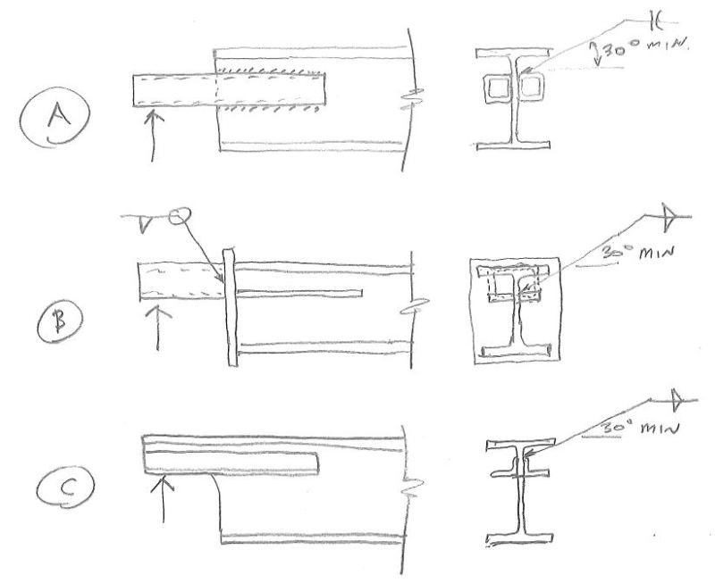
Here's a few other ideas:

Three_ideas_ubbgfc.jpg


Check out Eng-Tips Forum's Policies here:
faq731-376
 
For 2.5", I like something like JAE's option C but with a slotted horizontal plate rather than angles. It's more costly but that way you're not limited to dinky little L1.5's (maybe L2.0's depending on k distance). How shear challenged will you be here? I'm wondering if that's why you went double tube (4 webs).

I like to debate structural engineering theory -- a lot. If I challenge you on something, know that I'm doing so because I respect your opinion enough to either change it or adopt it.
 
After all the great responses (JAE's sketches were really good examples), I have really been thinking on how to make this work with the least amount of fabrication. Attached is a fully bolted seat style connection. Anyone see any issues with this.

 
 http://files.engineering.com/getfile.aspx?folder=4e82ed91-8899-4ff1-a653-0118a44c737e&file=07-28-16_Beam_Seat_Connection_at_Joist_Girder.pdf
That's basically a bolted version of the transverse seat angle that I mentioned above. As I indicated there, the flexibility of the angle leg makess it a bit hard to know how concentrically you're delivering the load to the joist girder. I assume that you want both girder top chord angles participating. If so, I would at least run the seat angle flange an inch past the vertical leg of the far chord angle.

I favor having the seat angle welded to the beam web. That said, you're version might make for easier erection if you've got the same condition on each end of the beam. If you go with botls, it will be a bolted moment connection. As such, I'd recommend a two column, two bolt pattern at minimum. This detail presents a difficulty analogous to your original detail. Namely, it's tough to know how prying etc pan out through the various parts of the connection. Just now it's an issue for the bolts rather than the welds.

Given what you're doing, you may find this article helpful: Link


I like to debate structural engineering theory -- a lot. If I challenge you on something, know that I'm doing so because I respect your opinion enough to either change it or adopt it.
 
Status
Not open for further replies.

Part and Inventory Search

Sponsor