Continue to Site

Eng-Tips is the largest engineering community on the Internet

Intelligent Work Forums for Engineering Professionals

  • Congratulations KootK on being selected by the Eng-Tips community for having the most helpful posts in the forums last week. Way to Go!

create associative curves in 3D for wire routing

Status
Not open for further replies.

ranjithbelur

Automotive
Mar 17, 2013
43
Hi, I have been given a work in which I need to create a wire with several bends using curves(without using sketch and the curves are not in one plane), and the bend radius should be parametric(fillet in Basics curves wont update with the change in adjacent curve length), Is there any method for creating this type of curves(we do not have licence for mechanical routing). Thanks in Advance.
 
Replies continue below

Recommended for you

Please include your NX version when posting for help.

Assuming you're using a version with NX that has this, Associative Arcs work for us but we typically do not completely re-route the path to the point that the arc's plane cannot be defined (in other words, our bends are planar). We also have the straight section endpoints meeting to form the intersection at the bends and use Follow Fillet with our Curve Rule.

Tim Flater
NX Designer
NX 9.0.3.4 Win7 Enterprise x64 SP1
Intel Core i7 2.5GHz 16GB RAM
4GB NVIDIA Quadro K3100M
 
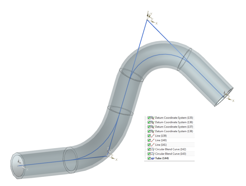
You can create lines and arcs in 3D space that are associative to each other. To model wires, I often use the line command to model the constrained part of the wire, then use bridge curves to connect the lines. Bridge curves can smoothly connect non-planar curves and result in a fairly good approximation of what an unconstrained wire will look like in the real world. It offers some control over the shape, but you will not be able to directly control the radius. If parametric radius control is really needed between 2 non-planar curves, the "circular blend curve" may help. If I remember correctly, this creates a spline that essentially lies on a cylindrical surface; when projected along a certain direction, the spline will appear to be an arc.

www.nxjournaling.com
 
Yup we basically use the method cowski describes, datum csys constrains the lines start/end points, circular blend curves between the lines with prescribed radii.

circular_blend_curves_tpo6jo.png


Status
Not open for further replies.

Part and Inventory Search

Sponsor