SoFloJoe
Structural
- Apr 3, 2018
- 76
I am working on a beam design that has dynamic loading for a trolly monorail design.
The structure already exists, the facility is upgrading their trolly crane system and I am analyzing this existing structure to make sure it can handle the new loads.
I have ran the loads and it all checks out, deflection is good, shear and moments are within limits per Florida Building Code and CMAA. But following AISC Steel Manual (14th ed) the Lateral-Torsional buckling is not working out for me. The verbiage is a bit confusing and was hoping that I can get some clarification here.
My process is as follows:
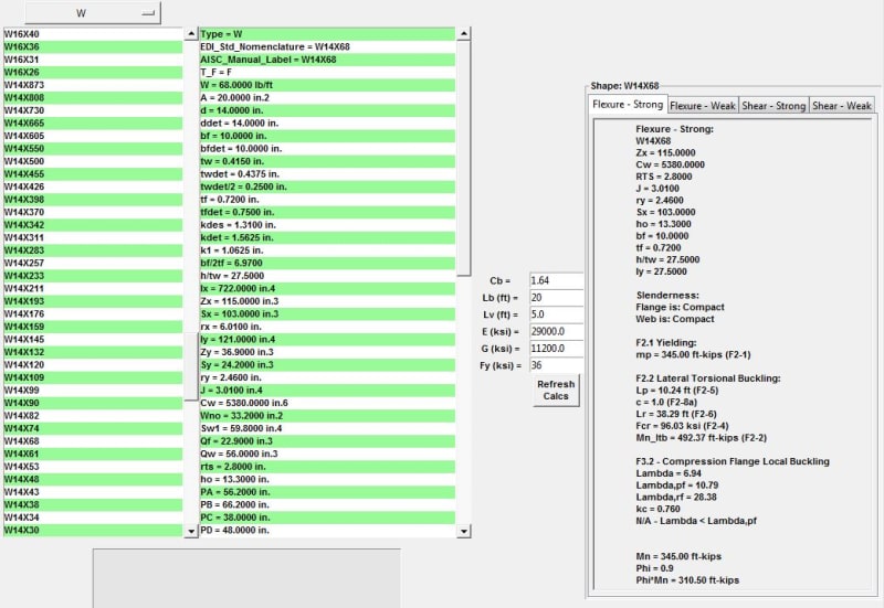
- It is an I-beam W14x68
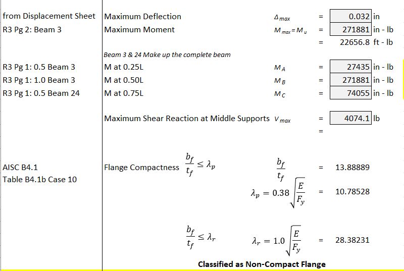
- Per Table B4.1b Case 10 it is classified as a non-compact Flange
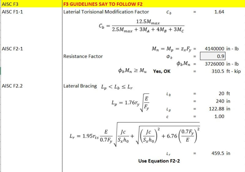
- Per F3, it states to follow F2.2 procedure. But what about F2.1?
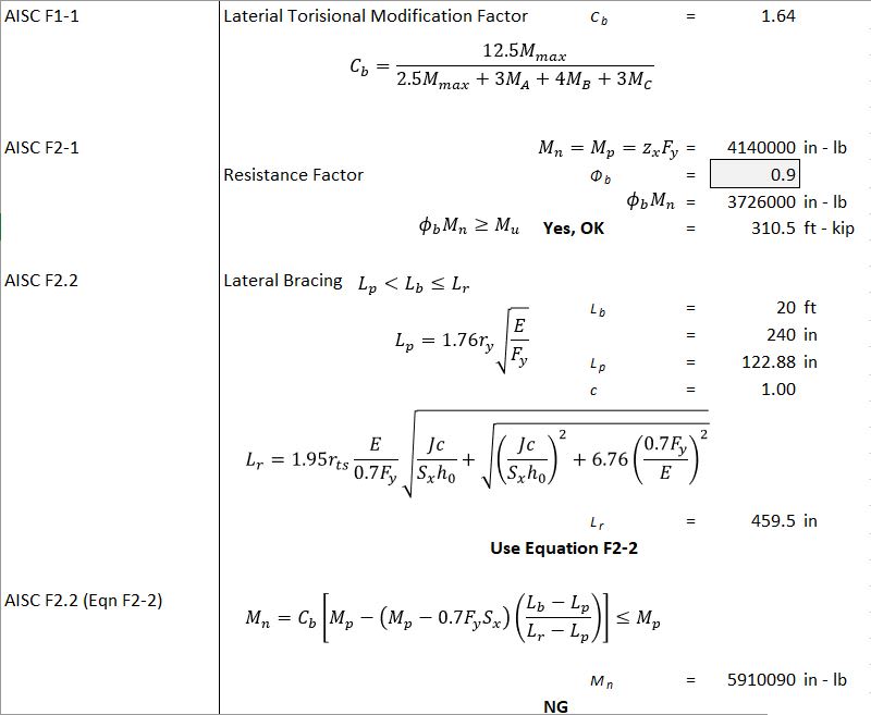
- Cb = 1.64
- This is where it gets confusing, AISC states that Mn = Mp = FyZx and also states that Mn shall be the lower value obtained. But the equation F2-2 uses both of these variables. I am right now assuming that Mp = FyZx (F2.1) and Mn will be the result of equation F2-2. Though the result of F2-2 should be < or = to Mp. And it is not per my calculation. Is my assumption incorrect and have I reversed Mp and Mn? Am I even using the right Mp?
- I also looked up the member using table 3-10, my unbraced length is 20ft and available moment using LRFD is 310.5 ft-kip. This puts the W14x68 well within the limits.
I am not sure what to do. If the Lateral-Torsional Buckling is indeed outside the limits then the only option other than switching out the i-beam that I would think of would be to cut the span with additional support but this will not make the client happy, are there any other options?
Below are clips from my excel to better explain. Thanks in advance for your help!


