Continue to Site

Eng-Tips is the largest engineering community on the Internet

Intelligent Work Forums for Engineering Professionals

  • Congratulations waross on being selected by the Eng-Tips community for having the most helpful posts in the forums last week. Way to Go!

Standard formula for double cantilevering beam 3

Status
Not open for further replies.

Iasonasx

Structural
Jun 18, 2012
119
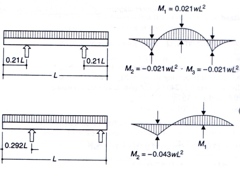
I thought about applying double cantilevering to minimize the material for a small structure, but I don't seem to find a standard formula for the deflection of this beam (see figure - I refer to the case on top although if formulae for the maximum deflections for both cases are available I would appreciate having them both)
Thank you!
Scan-180930-0001_aqa1dk.jpg
 
Replies continue below

Recommended for you

Maybe it is in some manual, but it is not in the textbook I got the diagrams from. Table 3-2 of the AISC does not have these scenarios. I did not think about searching internationally, but the Italian reference you made is good. I will not have much problem translating things as obviously "J" is the moment of inertia instead of "I" that we use here, etc. Thank you very much for your response.
 
IMHO, your examples are very limited in application, having specific geometry and not algebraic generalised geometry (like overhang = "a" and "b"). IMHO you should be able to calc these yourself, (the first case simplifies to a propped cantilever) and both examples are only SS beams (not sure why you say "cantilevering", unless it refers to the overhang).

another day in paradise, or is paradise one day closer ?
 
Just use superposition of several simple standard single side cantilever deflection formulas and any symmetry that exists, factor in the deflection at the second cantilever from the loading on other members based on the rotation at the support. Work out all the constituent load cases and add all the deflections together for the final deflection.

Remember to look at all loading scenarios, load on two cantilevers only, load on main span only, load on main span and one cantilever, load on single cantilever, load on all spans. Each of these may govern for a particular location/span configuration.
 
There's the option of directly calculating the overhang (cantliever) moments and then using the AISC beam diagram for a beam with uniform load and variable end moments (#32 in the LRFD 2nd Edition).
 
substituting overhang loads will change (albeit slightly) the deflections of the beam

another day in paradise, or is paradise one day closer ?
 
The first diagram in the original post is unusual because the dimension 'L' is the overall length of member rather than the span between supports. If 'L' is the span between supports, M1 = 0.0625wL[sup]2[/sup] rather than 0.021wL[sup]2[/sup]. M2 and M3 would be numerically equal to M1 and the sum of M1 and M2 or M1 and M3 would be wL[sup]2[/sup]/8 which every engineer recognizes as the formula for uniform load on a simple span. It is not wrong to label the diagram as in the original post, but if deflections are to be calculated, it is much simpler to use standard labeling.

The labeling in the second diagram is not correct by any standard. The dimension 'L' does not extend to the right end of the beam; it should extend to the right hand reaction and again, it would be better to use 'L' as distance between supports with cantilever dimensioned separately.

Deflections are readily calculated using moment/area theorems combined with simple span or cantilever deflection.

BA
 
To answer the concern about the labeling, these diagrams come from Schodeck's book named "Structures" which is used extensively in Architecture programs. Dr. Schodeck is a professor at the Harvard School of Design. He has his own ways like we all do. I would like to thank all of you for your input.
 
None of this made much sense... I was confused with the first pix and that the cantilever moment would be q(0.21 L)^2/2 and not 0.21 q L^2... and it just got worse... Must be the training that Architects get.

Dik
 
@dik, Maybe, however, Daniel Schodeck has a PhD in Structural Engineering so I cannot quite see how this goes on architects really.
 
Deflections are readily calculated using moment/area theorems combined with simple span or cantilever deflection.

Or superimpose standard formulas for deflection of simply supported span due to UDL and deflection due to constant moment for case 1 or linearly reducing moment for case 2.

Doug Jenkins
Interactive Design Services
 
Iasonasx;
You asked about deflections. In the case of the double cantilever beam, the deflection correction in the span due to M2 and M3 is M2(span)[sup]2[/sup]/8EI.
Since span = L(1-2*0.21) = 0.58L, the reduction in central deflection due to M2 and M3 is 0.021wL[sup]2[/sup](0.58L)[sup]2[/sup]/8 = 0.000883wL[sup]4[/sup]/EI.
The simple span deflection of the span is 5w(0.58L)[sup]4[/sup]/384EI = 0.001474wL[sup]4[/sup]/EI.
So the net deflection in the central span is 0.001474wL[sup]4[/sup]/EI - 0.000883wL[sup]4[/sup]/EI = 0.000590wL[sup]4[/sup]/EI or approximately 40% of the simple span deflection.

The slope at each support, theta = w(0.58L)[sup]2[/sup]/8EI * 0.58L/3 - 0.021wL[sup]2[/sup]*/EI * 0.58L/2 = 0.00813wL[sup]3[/sup]/EI - 0.00609wL[sup]3[/sup]/EI = 0.00204wL3/EI.
The cantilever deflection is reduced by theta*0.21L = 0.000428wL4/EI as a result of the slope, theta.
Deflection at free end = w(0.21L)[sup]4[/sup]/8EI = 0.000243[sup]4[/sup]/EI - 0.000428wL[sup]4[/sup]/EI = -0.000185wL[sup]4[/sup]/EI, so maximum deflection of each cantilever = -0.000185wL[sup]4[/sup]/EI (upward).

Unless I have made an arithmetic mistake, which is quite possible, the end of each cantilever deflects upward, so the maximum deflection occurs at midspan.

BA
 
BTW, in the sketch i posted (since I don't know the correct tech terms):
1 - deflection : is the deflection at the edge or at mid-span
2 - elastic line : is the deflection in any point you like (it is the equation of the deformation)
 
Iasonasx said:
Maybe, however, Daniel Schodeck has a PhD in Structural Engineering so I cannot quite see how this goes on architects really.

Then it reflects badly on engineers as well as architects for having selected the book...

Dik
 
Unless this is a homework problem or a learning exercise, why not use the money you would be billing on solving this problem and buy a simple beam program?
No disrespect intended, just trying to be practical.
 
A beam program is a good idea, but a simple moment distribution in Excel would also get the job done. If set up correctly, it will work for any span and overhang lengths and any load magnitude.
 
The right tool sort of depends on what you're trying to achieve. If you know the cantilever lengths, than any of the methods described above will work easily enough. However, if you're trying to optimze the cantilever length, that's a little trickier. I picked up one method (here, can't recall who) that I'm quite fond of because it works for any loading condition:

1) Calculate support reactions.
2) Move supports out to ends of beam fictitiously and calculate deflections.
3) Add real support reactions to beam described in #2 as loads and subtract those deflections from the deflections from #2.
4) Translate your deflections vertically so they are relative to the supports rather than the cantilever tips.

That said, if this is a practical work problem, I support XR's suggestion of using software. You can download RISA2D and run it in demo mode forever. That should be ample horsepower for this kind of problem.


I like to debate structural engineering theory -- a lot. If I challenge you on something, know that I'm doing so because I respect your opinion enough to either change it or adopt it.
 
@BA ... is M2 = 0.21wL^2 (as per figure) or (0.21L*w)*0.21L/2 = w(0.21L)^2/2 ... just asking ('cause the methods you guys use I haven't used in 30+ years)

another day in paradise, or is paradise one day closer ?
 
@dik, Well, I guess based on your standards it reflects badly on Harvard university too that hired him a few decades to be a professor there. These comments were unnecessary, and your responses were utterly useless. What Dr. Schodek has in his book, is two scenarios where the positive moment and the negative moment will be equal (if we have stationary loading), and thus the Mu is minimized for the average w. I found it a very interesting condition that is not in the standardized diagrams that we have in users manuals such as the one by the AISC on table 3-2. Frankly, I find some of those loading diagrams more outlandish than those in the book of D. Schodek. The post was not intended to give food for criticism to the practice of architects, engineers, or academics. For that type of postings there is facebook, not this forum which I consider to be a virtual space where we all exchange information as professionals. If for any reason you don't like the question, feel free to skip it and find another one. Please try to not be disrespectful, especially to such prominent figures in the discipline such as late professor Schodek because all it does in the end is to reflect on your own demeanor.
 
Status
Not open for further replies.

Part and Inventory Search

Sponsor