Eng-Tips is the largest engineering community on the Internet

Intelligent Work Forums for Engineering Professionals

  • Congratulations waross on being selected by the Eng-Tips community for having the most helpful posts in the forums last week. Way to Go!

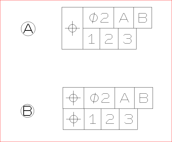
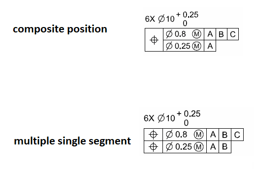
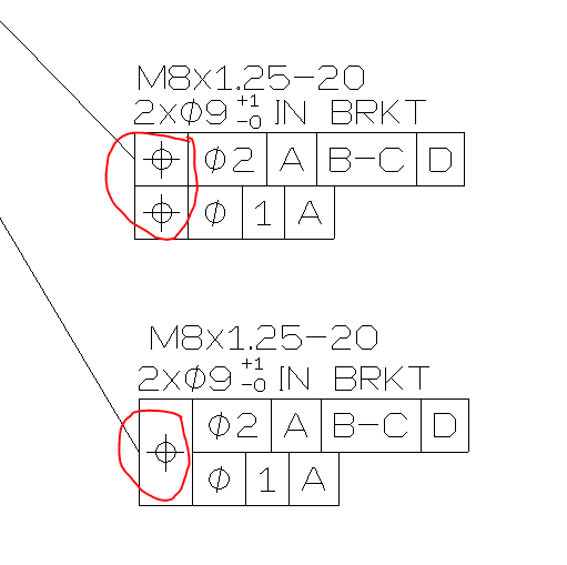
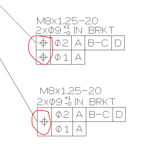
Geometrical Tolerance structure...... 4

Status
Not open for further replies.

CAD2015

Computer
Jan 21, 2006
1,926
US
Hi,

Which option is the right one: A or B? Or both?


image_hatm1q.png


Thanks!

CAD 2015
 
Replies continue below

Recommended for you

Both are wrong

"For every expert there is an equal and opposite expert"
Arthur C. Clarke Profiles of the future

 
Both are wrong because you're using numbers along the bottom. But if you're asking about the difference between one position symbol and two position symbols, that can make a big difference. I can't say which is correct because it would depend on what you're trying to control.

John-Paul Belanger
Certified Sr. GD&T Professional
Geometric Learning Systems
 
To beat a dead horse and further what John said: A looks like an attempt at Composite Position Tolerancing (single combined position symbol) and B looks like an attempt at Multiple Single Segment Position Tolerancing (two separate position symbols). Again CH and John are correct, the use of numbers instead of letters for datums is improper and not allowed per Y14.5 section 3.3.2 - only single/double alpha series are allowed.

See below for proper examples of each:

composite_vs_mss_ypienv.png
 
I apologize for giving the most vague answer so far, but I cannot help but question OP's motives.

I would really like to know, what is the backstory behind the question?

What is the standard framework (ISO, ASME, local country / company standard, etc.)?

Is there actual part behind the question, what is the function, how exactly the features to be controlled are related to referenced datum features?

Otherwise the question looks more like an attempt to settle a bet, or get quick help with the homework.

OP, please give us better understanding what the problem is and you may actually get better help :)

"For every expert there is an equal and opposite expert"
Arthur C. Clarke Profiles of the future

 
Belanger was right. Very good intuition.
Let me ask the same question, placing the right elements:

image_fwywak.png


Which option is the right one: The upper on or the lower onw? Or both, each option having different meaning.
If the last option it the right one, when should be they applied?

CAD 2015
 
Both schemes CAN (depending by the physical configuration) have the same meaning.
 
CAD2015,

You still have a "1" improperly located in both lower control frames. Assuming you actually mean the below, there is no way we can answer which one is "right" or "correct" - both are correct per the standard (as in legal or allowable - as long as they are applied correctly) while accomplishing different things.

I'm going to gloss over the "IN BRKT" note as I'm not sure what it applies to and I'm not going to try and guess.

It sounds like you need to familiarize yourself with the concepts of Composite and Multiple Single Segment Position Tolerance. ASME Y14.5 sections 7.5.1 (Composite Positional Tolerancing) and 7.5.2 (Multiple Single-Segment Positional Tolerancing) are going to be your friend. These are both methods of separately controlling a pattern as a whole as well as the individual features which make up that pattern relative to each other - they each accomplish this in similar, but different, manners. Most all of the information you need on this is contained in these sections of the standard.

composite_segment_syxikf.png
 
I would like to amend my initial statement.

1) I agree with greenimi - depending on the configuration they can possibly have the same result. As I said they are similar concepts and there is some overlap.

2) When I said theres no way to tell which one is right or correct - I mean to say that as long as each is correctly applied, it is up to you the designer to determine which is correct based on part function. Perhaps if we had more information on the drawing and application we could take a stab at which one we believe to be correct but ultimately its up to you to determine which one best captures functional intent.
 
CheckerHater said:
...I cannot help but question OP's motives.

I would really like to know, what is the backstory behind the question?

What is the standard framework (ISO, ASME, local country / company standard, etc.)?

Is there actual part behind the question, what is the function, how exactly the features to be controlled are related to referenced datum features?

Otherwise the question looks more like an attempt to settle a bet, or get quick help with the homework...

I would argue that his motives are not important as in most cases a search for knowledge is a good thing regardless of the bet. Further, anyone who actively searches out a GD&T forum and asks questions should be welcomed with open arms... Our kind are few in number. :D

I'm not a vegetarian because I dislike meat... I'm a vegetarian because I HATE PLANTS!!
 
To expand on chez311's post, the call-outs have two different meanings:

[ol 1]
[li]Two position tolerances stacked on top of one another:
Both position tolerances are independent requirements. They must both be met for all features independently.

If you have a pattern of M8x1.25-20 screw threads, the center of the pitch diameter of each thread must be positioned relative to the primary (A), secondary (B-C) and tertiary (D) datums within 2mm. The threads must also be positioned relative to the primary datum (A) within 1mm.

[/li]
[li]Single position tolerance with two values (composite position tolerance):
A composite position tolerance is a different animal which applies a specifically to pattern of features.

This tolerance would position an entire pattern of screw threads relative to the primary (A), secondary (B-C) and tertiary (D) datums within 2mm. The individual thread pitch diameters in the pattern must then be positioned relative to one another within 1mm. The orientation of the screw thread pitch diameters is also controlled relative to datum A within 1mm.

[/li]
[/ol]

I'll borrow chez311's image for reference.
composite_segment_syxikf.png


The second type of control can allow the pattern of features to float around a bit, while ensuring that the mating part will still bolt together with the hole pattern. This is helpful in quite a few situations. In the example above, a composite profile doubles the position tolerance on the hole pattern without making the holes bigger on the mating part (and sacrificing crush area).

As others have mentioned, I'm not sure what the 9mm diameter applies to, but maybe in the context of the whole drawing it would make more sense. Also, I assume that this is a hole pattern: If so, the screw callout is missing the number of screws (??x M8x1.25-20).
 
I'm assuming that the callout is referring to a 9mm diameter hole for an M8 x 1.25 screw. This is an awkward arrangement.
 
Status
Not open for further replies.

Part and Inventory Search

Sponsor

Back
Top