Continue to Site

Eng-Tips is the largest engineering community on the Internet

Intelligent Work Forums for Engineering Professionals

  • Congratulations KootK on being selected by the Eng-Tips community for having the most helpful posts in the forums last week. Way to Go!

Crane Runway Beam - Lateral Deflection

Status
Not open for further replies.

m1ke99

Structural
Nov 3, 2013
12
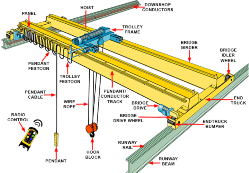
I'm evaluating an existing building for an increased crane capacity. Client wants to go from 30 Ton to 35 Ton. Overhead double girder, top running.

Everything is looking okay, except for lateral deflection on one of the crane runway beams. The runway beam on one side is on the exterior gridline of the building and laterally braced at the columns. The other runway beam is connected with a horizontal truss to the adjacent runway beam and therefore much stiffer for lateral deflection.

Is it okay to assume the lateral (side thrust) loads will be distributed to the stiffer runway beam. Or, does each runway beam need to meet the deflection criteria separately?
 
Replies continue below

Recommended for you

I'd design each beam to meet the criteria separately. Among other things in the crane assembly, the wheels have enough width/play in them where they can slide a bit and transmit force. Depending on how much the deflection is.....that could transmit force without help from the other side.
 
OP said:
Is it okay to assume the lateral (side thrust) loads will be distributed to the stiffer runway beam

I feel that this is okay and, really, pretty clever. I have a hard time imagining a trolley that couldn't transmit the load attributed to one side over to the other axially. The very fact that the stand alone beam doesn't have the stiffness you're looking for probably also means that it would't attract tons of load in the process of taking up some lateral slack if any comes to pass.
 
On a new design type item, yes I would ensure both meet. In an instance like this, I tend to be a little more liberal. Does the runway beam work for lateral deflection under the original 30Ton crane? If so, how much do you exceed it by now. If not, how much did it exceed by originally?
 
Ditto on what WARose said. The "slop" in the wheel contact is an issue in addition to 'straight alignment' of the rails.
 
I'm with kootk. You aren't going to see harmful deflection in one runway without engaging the other.
 
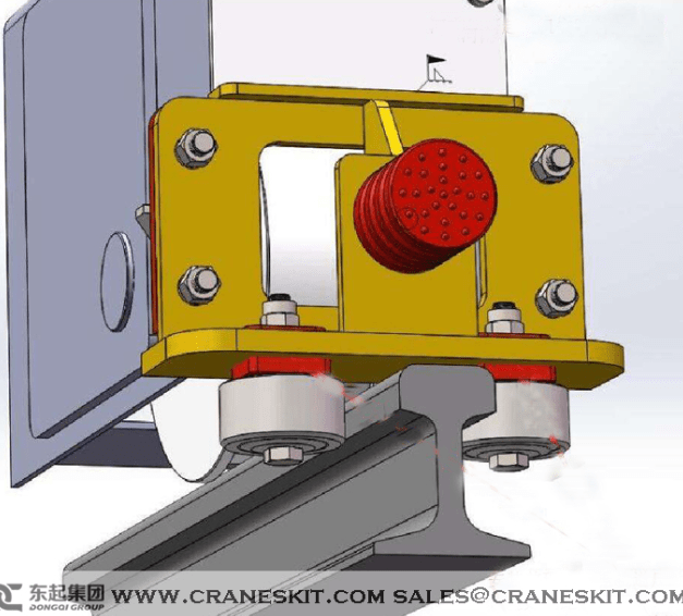
Does the amount of allowed lateral deflection exceed the possible slop in the wheel contact. For example, a 50' runway beam is allowed to deflect more than a 20' one I think. The 50' beam may be ok, but not a 20'. If your wheel has a "cheek" on each side your idea is much closer to working than if there is a "cheek" on one side only. 1-side only would not appear to work. I have seen cranes with 1 cheek but I think they ere generally not very heavy lifts. Underhungs most always have to have 2 cheeks I think.
 
What about the crane itself, is it designed to transfer 100% of the lateral on one side only? Maybe that’s the way it ends up being anyway due to the “slop” discussed above. Probably would be more of a wear and tear kind of issue.
 
R247 said:
For example, a 50' runway beam is allowed to deflect more than a 20' one I think. The 50' beam may be ok, but not a 20'.

I agree. Regardless of which side of the crane is doing the resisting, both sides need to keep curvatures below whatever level would cause the wheels to bind. L/400 or whatever. I'd be pretty surprised if the stiff truss on the one side didn't restrain both sides adequately but, yeah, it's something worthy of consideration.
 
What about the crane itself, is it designed to transfer 100% of the lateral on one side only?

I can tell you (as someone who has looked at a lot of crane manufacturer's drawings) the answer to that is a big "no". The whole problem with the "one side" approach is.....it assumes a perfectly rigid body (above) transferring these forces. That's not how a crane is built.
 
WARose, I almost wasn't going to comment on this thinking that the crane would be able to handle the lateral on one side without much issue - thank you for the info, good to know.
 
I think it is better to make both rail beams' deflection meeting the requirements. Maximum lateral load is transferred to one rail beam when trolley with payload stops near the end of the bridge. The lateral load on the other rail beam could be neglected for the wheel pressure on the beam is small.
 
CANPRO said:
What about the crane itself, is it designed to transfer 100% of the lateral on one side only?

WArose said:
I can tell you (as someone who has looked at a lot of crane manufacturer's drawings) the answer to that is a big "no". The whole problem with the "one side" approach is.....it assumes a perfectly rigid body (above) transferring these forces. That's not how a crane is built.

Clearly I am in need of some educating this morning. So we're saying that bridge girders are incapable of transmitting axial loads along their lengths when those lateral loads originate along their lengths? What am I missing here?

c01_in4vgs.png
 
Clearly I am in need of some educating this morning. So we're saying that bridge girders are incapable of transmitting axial loads along their lengths when those lateral loads originate along their lengths? What am I missing here?

Without getting into the numerous issues of varying tolerances of all the parts involved in a crane and so forth.....to use a very concrete example: how about crane skew? Since the wheel is wider than the rail, it isn't unusual at all to see wear on the inside rim of wheels from it hitting the rail. You think that always happens simultaneously and with the same level of force to the other rail? No. Ask any crane service people and they will tell you the wear is never perfectly even and is typically worse on one wheel than the other. More so as the wheel bearings get older. (Bearing movement, wear, and slip are other issues which will ultimately contribute to this as well.)


SHU said:
Maximum lateral load is transferred to one rail beam when trolley with payload stops near the end of the bridge. The lateral load on the other rail beam could be neglected for the wheel pressure on the beam is small.

That's an interesting point. The lateral load isn't honor bound to ride along with the vertical load but that will be the natural tendency. The lightly loaded truck isn't going to see uplift or anything but, if one deems there to be a meaningful risk of the lateral loads overcoming the keying between wheel and rail at the unloaded end, that warrants some consideration. Might be a good application for a clever detrailment prevention device.

c01_orann6.png
 
To me, the lateral load from the lifted load has to travel along the bridge girder but it is not obligated to travel as tension or compression. That is why I mentioned 2 cheeks versus 1 cheek. By cheek, I am referring to the increase in wheel diameter on each side of the rail that keeps the wheel from running off the rail. I have seen wheels with 1 cheek on the inside for example. In those, the cheek that winds up pushing sideways on the rail is controlling some of the lateral force and the friction is controlling the rest. The wheel friction is not the same since I can travel the lifted load to an extreme end. Wheel friction from crane weight is one part, friction from lifted load is another. Which cheek presses against the rail may determine if if lifted load lateral travels left or right down the same bridge girder (tension or compression) .

The lateral load from crane travel along the runway is not obligated to travel down the bridge girder. That force is misalignment, wear etc.
 
WArose said:
Without getting into the numerous issues...

None of this really addresses my apparent misunderstanding about the girder being axially rigid and able to transfer axial loads. Can you explain that part to me as that's the bit that's really got me scratching my head?

WArose said:
how about crane skew?

How is asymmetrical lateral stiffnes here going to make crane skew worse than it might otherwise be given that the overall lateral stiffness ought to be quite good (truss)? As I understand it, crane skew is most often caused by the crane itself rather than the runway.

WArose said:
Since the wheel is wider than the rail, it isn't unusual at all to see wear on the inside rim of wheels from it hitting the rail. You think that always happens simultaneously and with the same level of force to the other rail? No. Ask any crane service people and they will tell you the wear is never perfectly even and is typically worse on one wheel than the other. More so as the wheel bearings get older. (Bearing movement, wear, and slip are other issues which will ultimately contribute to this as well.)

While I still don't see how symmetrical runway lateral stiffness solves this, I wouldn't be at all surprised to find that the asymmetry resulted in an unusual wear pattern. Is that a deal breaker though? I'd think it would be a matter or presenting the options to the owner:

1) Leave the asymmetry as and accept some risk of some nebulous, atypical wear patterns in the future OR;

2) Spend some money now and make it symmetrical.

Given that the new crane is 35 ton and they've been using a 30 ton without issue, I don't foresee a huge probability of a maintenance catastrophe coming to pass here. Lets also not forget that it's not as though the overly flexible runway beam has no stiffness at all. Moreover, unless we're willing to add a horizontal truss that sticks outside of the building, we're probably stuck with the asymmetry even if the flexy beam is brought up to spec.
 
WArose said:
.it assumes a perfectly rigid body (above) transferring these forces.

Is it perhaps that you're saying that there is not rigidity in the trucks? That I can agree with but, still, one way or another there has to be enough rigidity in the trucks to get the lateral loads out of the bridge and into the rails under normal circumstances.

 
Can you explain that part to me as that's the bit that's really got me scratching my head?

A crane is a bunch of parts put together. (It's not a injection mould.) The wheels are just one aspect of this.


How is asymmetrical lateral stiffnes here going to make crane skew worse than it might otherwise be given that the overall lateral stiffness ought to be quite good (truss)? As I understand it, crane skew is most often caused by the crane itself rather than the runway.

It's caused by both. Misalignment of either one can contribute to it. The bottom line is: one wheel can hit the rail and transmit force while the others are transmitting much less. In a case of the rail on the other side slipping (under a low coefficient of friction: i.e. steel on steel)......you won't get any help from a one side truss.

While I still don't see how symmetrical runway lateral stiffness solves this, I wouldn't be at all surprised to find that the asymmetry resulted in an unusual wear pattern. Is that a deal breaker though? I'd think it would be a matter or presenting the options to the owner:

1) Leave the asymmetry as and accept some risk of some nebulous, atypical wear patterns in the future OR;

2) Spend some money now and make it symmetrical.

Given that the new crane is 35 ton and they've been using a 30 ton without issue, I don't foresee a huge probability of a maintenance catastrophe coming to pass here. Lets also not forget that it's not as though the overly flexible runway beam has no stiffness at all. Moreover, unless we're willing to add a horizontal truss that sticks outside of the building, we're probably stuck with the asymmetry even if the flexy beam is brought up to spec.


From the structural engineer's standpoint, it makes sense to me to be conservative. I'm not sure I've ever seen anywhere in the CMAA where you can do this. If something went wrong, you could be questioned on relying on the crane to stabilize anything. Your steel supports it......not the other way around.

Furthermore, the OP hasn't said the years this thing has been in operation and it's level of usage (Class A, B, etc). If it's been in business for a while.....I wouldn't even consider a one-truss approach.
 
KootK said:
None of this really addresses my apparent misunderstanding about the girder being axially rigid and able to transfer axial loads. Can you explain that part to me as that's the bit that's really got me scratching my head?

I agree with you on this, KootK (or at least I share the same misunderstanding).

How else does a one-legged gantry crane work? There's no way you're making that stable without transferring axial force along the crane girder.

gantry-crane-design_sj2bkh.jpg


The_forward_island_of_the_queen_elizabeth_class_aircraft_carrier_being_attached_to_the_main_body_of_the_carrier.jpg


Ian Riley, PE, SE
Professional Engineer (ME, NH, VT, CT, MA, FL) Structural Engineer (IL, HI)
 
Status
Not open for further replies.

Part and Inventory Search

Sponsor