Continue to Site

Eng-Tips is the largest engineering community on the Internet

Intelligent Work Forums for Engineering Professionals

  • Congratulations KootK on being selected by the Eng-Tips community for having the most helpful posts in the forums last week. Way to Go!

TRANSFORMER CORE CLAMP GROUNDED. 3

Status
Not open for further replies.

WaltCSF

Electrical
Apr 14, 2019
2
In advance thanks for the help,
we found a grounded core clamp by measuring insulation resistance, what now? do the transformer should stop operation?, can someone explain what is the core clamp single ground for? what this result means? (500 V, <10kOHM)

thanks!

XFMR: 100 MVA, YnD1, 138/13.8 kV, GSU, ONAN
 
Replies continue below

Recommended for you

The transformer core should be grounded in a single spot during operation. In order to check for a single point ground, the jumper or strap that makes the single ground connection is lifted and the resistance between the core and the ground checked, with a Megger at 500VDC. Depending on your meter, that <10kOhm could be a zero value. Check again with a Fluke and see what you read.

If you have multiple core grounds, this can cause circulating currents and a DGA can reveal this problem. There are several ways of removing multiple core grounds. Old school methods involve using a DC welder to burn the extra ground open. Some will place a resistor network at the core ground strap connection. If you do indeed have multiple core grounds, it's best to check with the manufacturer and see what they recommend.

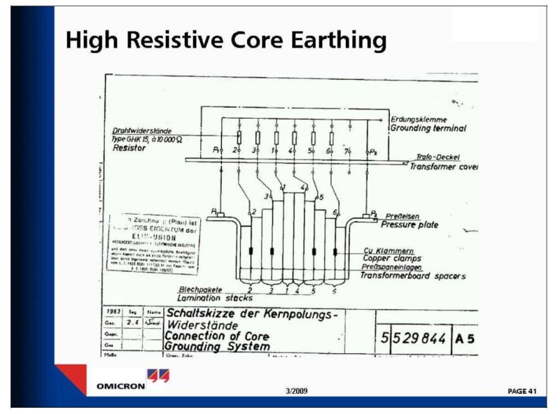
Some designs have intentional resistor networks in the core to ground connection (see picture).
core_ground_lcxy2s.jpg
 
Thanks for your Fast response thermionic1, we have core ground bushing and core clamp bushing, we have the low insulation resistance at the core clamp insulation, multiple core clamp ground can cause severe damage as well as multiple core grounds? I'm trying to understand specifically the core clamp multiple grounds consequences and failure mode, I appreciate your time with this topic [pc2]
 
Core(ie.core lamination stack) and core clamping structure are separately brought to cover terminal box through bushings and then grounded to earth at tank cover. Insulation resistance of core to G and core clamp to G and Core to core clamp are measured separately. As per C57.152-2013,minimum IR value recommended is 500 megohms at 1kV DC for new transformers. In old transformers it may come down to even 10 meghoms. When any of above IR value is zero, it means double grounding and circulating current may occur. Out of these three readings, core clamp to G is most significant and other two may not create much problem.When transformer is loaded, leakage flux from windings will impinge core clamps and induce voltages. When there are two grounds,this will result in heavy current flow, overheating metal. In large transformers, it may even melt metal at joints. Normally this will be detected by DGA check. If DGA is OK, it means, additional grounding is not creating damaging current flow.
So when above situation arises, there is no need for immediate shut down, but better to reduce load as much as possible so that circulating current will come down. Solutions: Open out the grounding at cover so that double earthing is prevented. With low IR values, some times cover grounding is done through a resistor to limit the circulating current, if any.
 
Status
Not open for further replies.

Part and Inventory Search

Sponsor