Continue to Site

Eng-Tips is the largest engineering community on the Internet

Intelligent Work Forums for Engineering Professionals

  • Congratulations Danlap on being selected by the Eng-Tips community for having the most helpful posts in the forums last week. Way to Go!

Masonry to Steel attachment 1

Status
Not open for further replies.

SteelPE

Structural
Mar 9, 2006
2,749
I have an existing building where the owner would like to install some new openings in the perimeter of the building. Code is IBC2015/ASCE7-10.

The existing building is 50’s to 60’s with riveted clear span gable roof trusses supported by perimeter columns and infill 8” CMU. The existing trusses/column connection contains a knee brace from the column to the roof truss (I’m thinking/assuming these knee braces resist lateral loads).

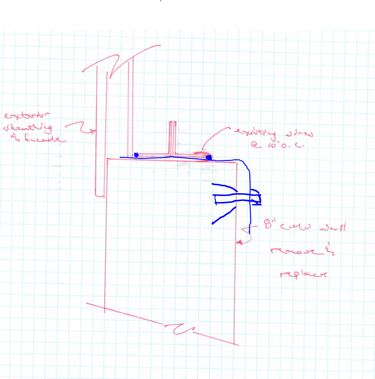
The owner would like to install 2 new overhead doors in the gable end of the building. Due to existing window locations, we think it’s better to remove the existing wall in its entirety and reinstall a new 8” CMU.

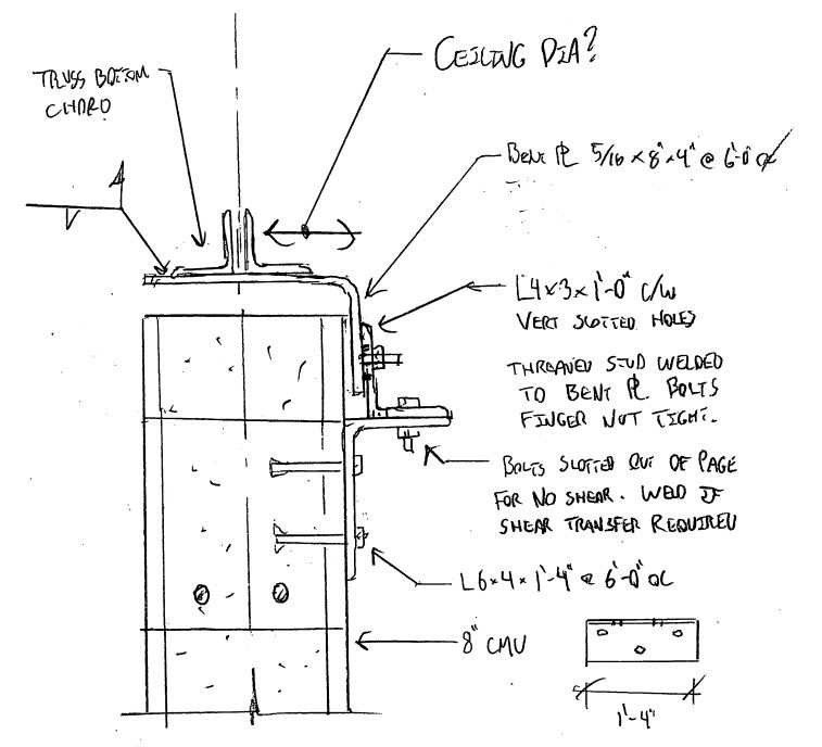
The issue I have in regards to attaching the new wall to the existing truss (see attached sketch). I have two options I usually default to in similar situations

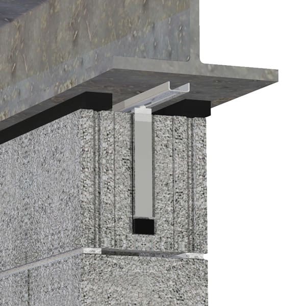
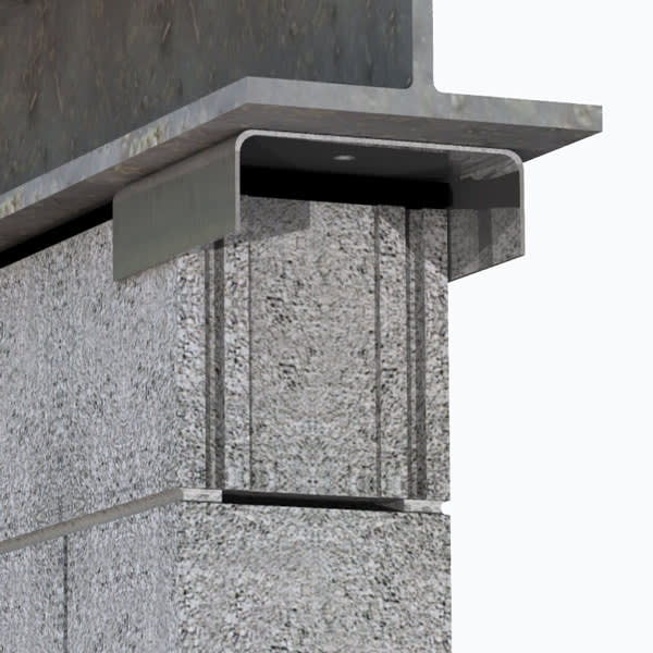
1) Come up with an angle/expansion bolt detail to attach the truss to the new CMU wall
2) Install nelson studs along the bottom chord of the truss and grout the nelson studs into a bond beam.

Both options are not great. Does anyone have a better detail for this situation?

The existing wall has wire ties at 10" o.c. +/- attaching the masonry to the existing truss (shown in the sketch).

At this point, CMU is the direction we have not plans to get away from the CMU so please do not offer a solution that uses other building materials.
 
 https://files.engineering.com/getfile.aspx?folder=2015d0c7-9c38-43ac-818d-fdb1751601cd&file=img387.pdf
Replies continue below

Recommended for you

Too bad you don't want other alternatives. Sounds like a great place to use light gauge...

But since you can't, your option 1 is probably best. Given its age, do you have any concerns with weldability of the existing truss? If not, maybe a continuous or intermitent bent plate that can be welded to the bottom chord and bolted to the CMU (long slotted holes in the vertical leg).

Capture_vzswqw.png
 
phamEng,

I actually never thought of using metal stud until I was writing the post. Unfortunately I have very little design experience with metal studs and there is no arch on the project so sizing of the studs would be my responsibility. Also, this is an automotive repair facility so durability is an issue (they need something that can take some abuse.

Is weldability a concern, I don't really know. The existing trusses are riveted together. I thought I saw a few welds around the structure for repairs that were made during the life of the building, but I am not sure. I was hoping for a detail that didn't require welding, but I am not sure if that is possible.
 
Powder actuated fasteners? It's an all shear connection between the plate/angle and the truss, so PAFs would hurt the net area of the tension chord less and be easier to install than a field drilled bolt hole. I'm not a welding expert, so I'll leave the research on steel chemistry prevalent in the 50s and 60s to you if you so choose (though I will shameless benefit from it if you want to come back and share!).

Sizing metal studs for an infill wall isn't bad, and you could specify impact resistant gyp for the sheathing.
 
Do not make rigid connections between the truss and the CMU wall. The truss needs breathe (temperature effect) and exercise (elongation due to loading/unloading), you should design a guide to allow the truss chord to move in axial direction, but limit movement in lateral direction; and leave a gap between the CMU bond beam and the bottom legs of the chord. Fill this gap with flexible material. The guide can be made of fastener similar to clamp for railroad track. A little research should be able to find suitable device.
 
I agree with retired13 and I like the holistic description of breathing and exercising. You want to minimize restraint on the CMU too, because it’s going to shrink then expand and contract with the weather, and the steel inside the building won’t. The truss and wall aren’t going to play well together so the less restraint between them, the less serviceability problems you’ll have. I can see why the wires would make an ideal connection.

Even a guide/bumper type connection would likely bind up despite your best intentions and prevent the free truss deflection and free in-plane movement that you want.

Would it be feasible to design the wall to span horizontally, maybe with intermediate pilasters?
 
What is the load path for the gable endwall wind force? How about the wind force along the truss?

When I run into this I'm always fighting the wind force resolution with the need for flexibility at the truss-to-wall connection. If I can, I span the endwall all the way up to the roof diaphragm. If you have a kneebraced frame at the endwall, it will be much more flexible than your CMU endwall, even with the doors in it. The shear force wants to go into the CMU.
 
JLNJ,

This is an existing condition. We are only adding openings below the existing truss that require removal and replacement of the existing wall. We are not changing the load path around, and we are not increasing the loads on any member, so technically, we don't have to be worried about what happens once we hit the bottom chord of the existing truss.

I understand about wanting the items to move separately, but I do nee to attach the wall to the truss for out of plane wind loads (which, if I were to guess, are around 100-150 plf (allowable) at the top of the wall. I would love to use an anchor from Hohmann and Barnard, but they don't quite have any that cover this condition. I can add a horizontal slot to the detail proposed by phamENG, but if I were to choose a slot connection I would slot the connection vertically.

This isn't the best situation, and I may just need to chose the lesser of two evils.
 
The proprietary partition top anchors designed for out-of-plane-only have a slotted track for in-plane freedom and a compressible gap at the bottom to allow vertical deflection. I suppose you could use that if you find a simple way to attach the track to the truss. But I’ve never trusted those dovetail track things to not bind up, same way I don’t trust that slotted hole connections will allow movement the way we hope.

44E673CA-CC11-4839-B144-20A2DA1A3BFC_arm1jg.jpg


The bent plate type does the same thing and may be simpler and easier to fix if it does bind up.

A17322ED-30CF-482C-BEFE-60DC47B97CFB_ocgwdx.jpg
 
bones, I was considering using a modified phamENG detail to reflect your second detail. I was thinking about installing two angles (maybe 4" long L6x4x1/4 LLH or a bent plate 7x3x1/4) at 2'-0" o.c. staggered. One angle would be toed down inside face, the other would be toed down outside face. I might try to get them to buy that detail. I can see them balking at it a bit as you might see the angle on the outside of the building.
7
If you look on the detail I provided, they currently have wire ties at 10" o.c. attaching the existing masonry to the BC of the truss...... these angle should do the same
 
I like the alternating direction idea - avoids the need to anchor into the block and minimizes the chances of the bolt binding in the slot (for the record, I meant vertical slots for deflection allowance).

As for it being exposed, can you set the block in half inch? Your sketch shows a facade coming down and lapping with the block. It's easy if the block is sitting on a turn-down slab or something similar; a little harder if it's passing the slab to a footing. If you can, then the facade may come down far enough to hide the angle. What's the calculated deflection in the truss? I know you're not modifying it, but it'll be important to get the vertical leg on your angle/bent plate and the gap between the block and the truss right (unless you're just going to match existing).
 
The nice thing about the bent plate is it’s like 12 gauge thickness, so you could attach each one to the truss with a few PAF’s. Quick and easy, and they don’t get in the mason’s way. Also thinner and easier to hide with siding.
 
So after some thought, this is what I came up with (I hope the image works):

img392_shl5mq.jpg


I think this solves almost all of the issues.
 
Alternate direction on angle (toe inside toe outside)
 
Seems like a decent detail. Might be a little challenging to build, having to keep the angles in just the right place while grouting.

I would extend the verts into the top course to provide a positive mechanism for shear transfer.
 
Oh yea...I guess that's what "alternate direction of angle" means....[banghead]
 
@SteelPE: What is the nature of the system that laterally braces the bottom chord of the truss? Horizontal trussing at the ceiling level? I wonder if that might be used to advantage. Also, in your latest detail, I'm concerned about the ability of the masons to wet set those clip angle + stud assemblies. You'd almost have to slide them in from the side as you go as you constructed that last course of block.
 
@SteelPE - I'm not buying the argument that you don't need to worry about the load path. If you take decent-sized section of wall down, put it back up, and design the wall restraining connection element, consideration of the stabilizing load path seems well within the standard of care. Maybe the judge and jury would disagree with me, I don't know.


Couldn't resist taking a swing at this.

- Lots of parts and pieces but easy to build on site. Everything could be done post-wall if desired.

- Sketchy reliance on slotted connections. For low stakes and an indoor exposure, I'm willing to bend on this.

- Easy potential to make an out of page shear transfer connection if desired.

c01_s19vdm.jpg
 
Status
Not open for further replies.

Part and Inventory Search

Sponsor