Navigation
Install the app
How to install the app on iOS
Follow along with the video below to see how to install our site as a web app on your home screen.
Note: This feature may not be available in some browsers.
More options
Style variation
-
Congratulations MintJulep on being selected by the Eng-Tips community for having the most helpful posts in the forums last week. Way to Go!
You are using an out of date browser. It may not display this or other websites correctly.
You should upgrade or use an alternative browser.
You should upgrade or use an alternative browser.
Early Days of the Power Grid 3
- Thread starter Mbrooke
- Start date
- Status
- Not open for further replies.
- Thread starter
- #2
- Moderator
- #3
- Thread starter
- #4
-
1
- #5
The development of protection took place according to the development of the energy systems and the devices used. Fuses were patented by Thomas Edison in 1890 and used in his DC electric distribution systems. AC relay protection and substation automation history go back to the beginning of the last century. A rought time table with a short historical background is shown on the following link for early protective relays development:
1899-1900 - One of the first electromechanical protective relays was produced. A definite time relay was installed in the Niagara Fall Transmission Project manufactured by GEC.
1909 Induction disk type inverse time current relays came into practice and the concept of directional discrimination of faults was incorporated.
1913-1918 Differential relay was developed using pilot wires for conveying information from line end-to-end
1920 Reverse current relay
1920-21 Polarized dc relays with better accuracy and sensitivity. Westinghouse manufactures this relay.
1923 Distance relay appeared in the form of impedance. Later, the induction type mho relays
1940’s showed the way into the development of relays using electronic devices.
1980's Was the era that starts the development the digital relays
- Thread starter
- #6
Was this just a definite time relay at Niagra or were they interlocked by pilot wires? The link appears to show something more complex.
BTW- I Googled the Niagara pic that brought me to a PAC world article. It seems like they had resistors in series with the gens? Was this for stability to keep available fault current down?
BTW- I Googled the Niagara pic that brought me to a PAC world article. It seems like they had resistors in series with the gens? Was this for stability to keep available fault current down?
-I read a company's annual report from around 1910, they boasted that it was the first year that they had not had a system wide blackout.
-In earlier systems I have the impression that the fact that two different 500kw generators might have different impedances and thus affect breaker ratings was not realized.
-At Niagara Falls opening the field breakers were once the only working way way to clear line faults.
-At the 1906 Cos Cob plant of the New York-New Haven electric railway line Westinghouse rebuilt the new generators three times before they got them to cope with the single phase load.
-In Philadelphia GE had to invent the phase balancer to cope with a single phase railway there.
-Between 1905-1930 NY Edison/Con Ed staff wrote a number of papers about interconnecting their plants until they appear to have recognized stability calculations.
-Symmetrical component analysis was not realized until somewhere 1915-1925.
-for line protection before the 1920's I think current balance relays between parallel transmission lines were considered the height of technology.
There was a long learning curve before electrical engineering matured. The 1900-1935 AIEE/IEEE transactions wittingly or unwittingly reveal a lot of this. HathiTrust has a comprehensive private book called Niagara Power by Edward Dean Adams. There is also a Kindle biography of Frank Sprague called The Birth of Electric Traction that touches on pioneering DC systems. He was commended for coming up with a paper way to find the best cost/voltage drop layout for electrifying a town. Previously the guys had been using trial and error on a nail board with model line resistors.
Bill
- Moderator
- #8
The technology was there. Not all of the smaller grids used the technology. Many smaller grids had more in common with distribution systems than with transmission systems.
Thanks for the link, Cucky2000
Bill
--------------------
"Why not the best?"
Jimmy Carter
Thanks for the link, Cucky2000
Bill
--------------------
"Why not the best?"
Jimmy Carter
- Thread starter
- #9
MBrooke If you are pointing to the "Overcurrent Releases" paragraph in the PAC World article I read the description as meaning the breaker progressively inserted the resistance until the current was low enough that the final contact could break it. At first Niagara's initial power exceeded what existing switches could break. I don't think the term Circuit Breaker even existed.
Bill
Bill
The Con Ed papers are scattered through the AIEE transactions. "Synchronized at the Load" was the theme of some of them, I was mystified by what the phrase meant. At a library (pre internet) I read the indexes and scanned the volumes to find articles of interest.
Bill
Bill
- Thread starter
- #12
Bill, thanks for clarifying. I'd wager a bet modern Alduti-Rupter switches can break more current than those Niagara "Breakers"
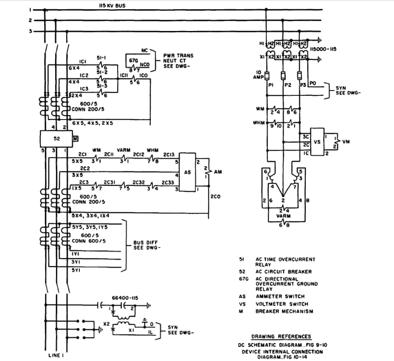
The single line diagram leaves me a bit confused if the lines were in normally closed parallel operation or normally open with auto throw over.
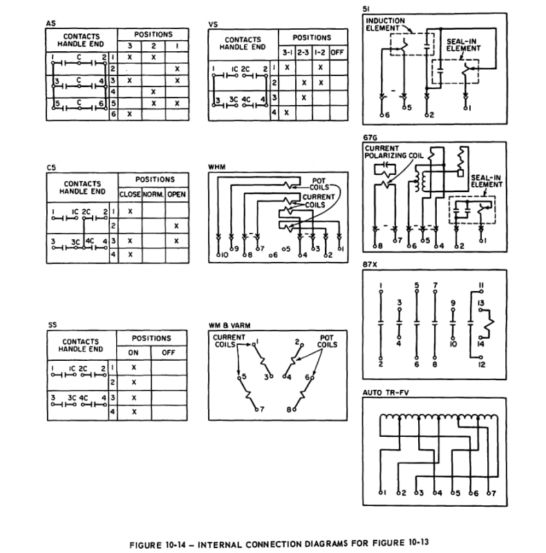
Anyway, reason I ask is I found some 60's drawing showing a power plant where the 115kv feeders are only protected via 51 & 67G relays- amp, volt selector switches/gauges and watt hour meter on each feeder. Everything screams islanded radial operation. I have to admit, it looks really elegant.
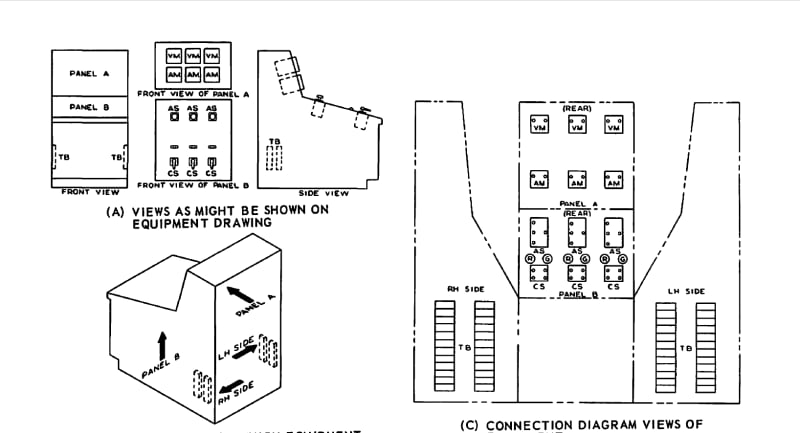
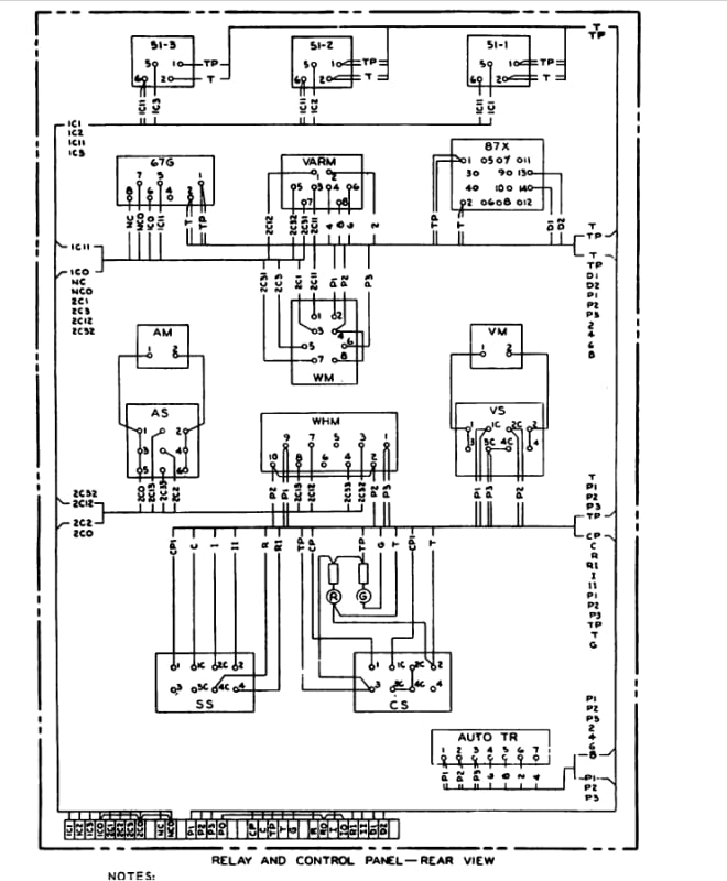
The control panel:


MBrooke, I should go back to your initial question. The early systems functioned fine without interconnections. They just had the reliability and outages one expects from todays isolated diesel systems.
Unlike today the customers didn't know of or expect perfect service, they were happy with the step up from gas lights/oil lamps/candles. The brightness, even lighting, cleanliness and low attention were big plusses. Electric salesmen truthfully pitched merchants on the increased sales that would result.
We had a four hour evening outage here a few weeks ago. We put a bunch of candles on a pizza pan on a glass table and could see around room easily but reading was uncomfortable. We enjoyed an old custom, we talked .
.
Bill
Unlike today the customers didn't know of or expect perfect service, they were happy with the step up from gas lights/oil lamps/candles. The brightness, even lighting, cleanliness and low attention were big plusses. Electric salesmen truthfully pitched merchants on the increased sales that would result.
We had a four hour evening outage here a few weeks ago. We put a bunch of candles on a pizza pan on a glass table and could see around room easily but reading was uncomfortable. We enjoyed an old custom, we talked
Bill
- Thread starter
- #15
But how did they keep early systems stable during a fault- especially with what I'm guessing were 10+ cycle breakers? I keep imagining a 0.5 cycle critical clearing time lol.
Why did the decide on operating the lines in parellel? I'd think normally open operation would have been a no brainier.
Why did the decide on operating the lines in parellel? I'd think normally open operation would have been a no brainier.
From "In 1895, the Niagara Falls Power Company began placing contracts with the Westinghouse Company for long distance electric transmission development and implementation. It included the building of transformers that could handle 1,250 horsepower and the stringing of overhead wires capable of transmitting 11,000 volts.
On November 15th 1896, the City of Buffalo joined the power grid being generated from Niagara Falls. It became the first long distance transmission of electricity for commercial purposes. With this new success, new industry moved into the area.
I remember reading - can't remember the reference - that the early fuses for the Niagra Falls project were open fuse wire, with one side being attached to a hinged board to allow the arc distance to increase. Later fuse wire on arc horns was used. All before oil switches were developed.
Fred
- Thread starter
- #17
- Thread starter
- #18
Here are two examples of fused horns in case readers are like HUH? lol. Last vid looks like it was bypassed perhaps but it gives you the general idea. This practice is now being phased out.
davidbeach
Electrical
Niagara Falls and Buffalo were latecomers, “long distance” “high voltage” transmission began in 1889 between Station A at Willamette Falls and Portland. 14 miles and 11kV, neither of which would now qualify as long or high, but back in the day it was a major milestone.
The first transmission lines were operated as radial backbones.
I have some material on the 5.1 kV ac single-phase, 25 km long, Tivoli - Roma transmission line, which started commercial operation in 1892.
As already said, as long as you have a point-to-point connection there was a little need for timely protections.
Parallel operation of different power plants was adopted some years later, as well as the first protection schemes.
Si duri puer ingeni videtur,
preconem facias vel architectum.
- Status
- Not open for further replies.
Similar threads
- Question
- Replies
- 4
- Views
- 2K
- Question
- Replies
- 3
- Views
- 6K
- Locked
- Question
- Replies
- 2
- Views
- 2K
- Replies
- 4
- Views
- 7K
- Locked
- Question
- Replies
- 2
- Views
- 407
