Continue to Site

Eng-Tips is the largest engineering community on the Internet

Intelligent Work Forums for Engineering Professionals

  • Congratulations KootK on being selected by the Eng-Tips community for having the most helpful posts in the forums last week. Way to Go!

Equivalent frame analysis question 2

Status
Not open for further replies.

Agent666

Structural
Jul 2, 2008
3,080
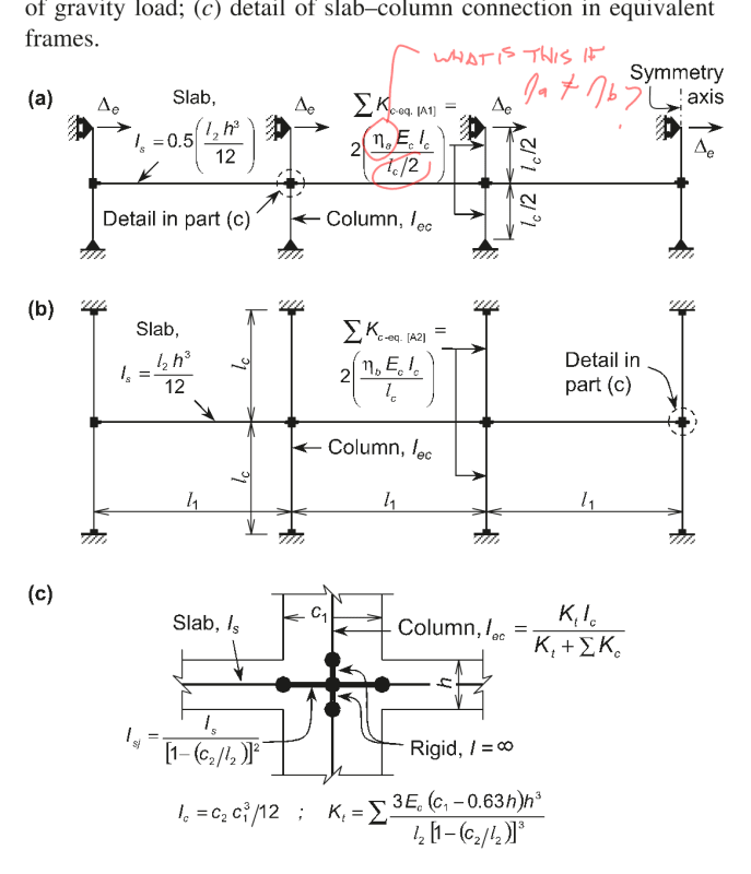
So I was working through trying to teach myself the equivalent frame method from ACI318, specifically looking at some of the examples in ACI421.2 related to flat plates. But for the life of me I'm not getting the same answer for Example 1 (see attachment below). In particular my main question is with calculating the equivalent column stiffness, does anyone agree with the ACI value, and if so where did I go wrong? I wonder if someone can take a look and see if they agree with me or if I've made some dumb mistake somewhere.

I will note that doing the analysis talked about for the unbalanced moment based on a accommodating a 0.75" drift gives me the exact same moment they get, so it leads me to believe I've made some mistake somewhere. But then I've reviewed a number of other examples I found online and in PCA notes and seem to be following the same procedure as far as I can tell with respect to undertaking an equivalent frame analysis.

Next question for anyone familiar with ACI421.2, when doing the lateral analysis to determine the out of balance moment, just wanted to confirm whether the bit of slab modeled inside the column also has the 0.25-0.5 stiffness reduction applied as per the slab span outside of the column? EDIT the reason I ask this is initially I applied the reduction tot his region also, but the only way I can get the same moment as the ACI example is to only apply the 0.5 reduction beyond the column area and use full I_s in the column region
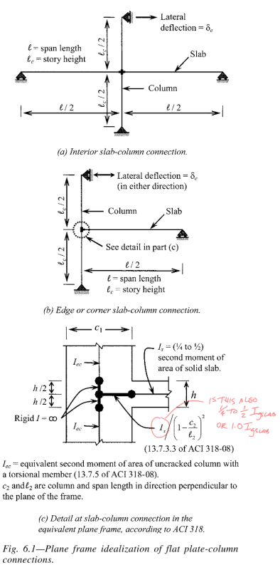
Annotation_2020-02-09_190855_usbfwr.png


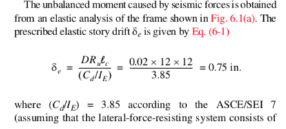
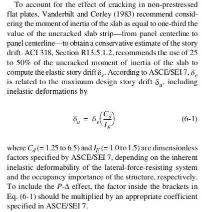
Thirdly, in the example attached, one thing that makes no sense to me given I don't practice in the states and are not really familiar with the inner workings of US loadings codes, is that they are checking this column/slab connection for 2% drift but then they come up with 0.75" drift when the elastic drift or compatibility drift this connection will see will be 2% x storey height of 12' = 2.88" drift (i.e. same as shear walls in building). Why is the drift being reduced, seems illogical to me if the floor system is going along for the ride to 2% total drift as stated? For example they are stating at 0.75" drift these upper limits are not applying, but they sure as eggs will if you push it to 2.88" drift...

Thanks for any input!
 
Replies continue below

Recommended for you

After a bit more reading I've noted one error I made, I also think I have the wrong equation for η for this situation. This screenshot from a Canadian paper suggests a different equation for η applies when looking at the equivalent frame for lateral loads and taking column heights at half the storey height.
Annotation_2020-02-10_060720_oi5ma2.png


Correcting the l_c/2 error (see updated attachment) gets closer but suspect I still have the η equation wrong and thats my issue. I understand what it generally represents as an effective stiffness factor but cannot find anything on how its calculated exactly? Can anyone lead me in the right direction here?
 
If I'm following properly the n is a factor to get you the K factor for the columns including the infinitly rigid zone.
Take a look at the Hardy Column Method/Analogy also if you can find a copy ACI SP-017 has a detailed calculation where they apply the method.

My Personal Open Source Structural Applications:

Open Source Structural GitHub Group:
 
Yeah I found that example in ACI SP17 but I'm not certain how to account for the fact that the analysis requires only half the column height when looking at lateral imposed displacement vs full height when looking at gravity analysis only.

If I work through the SP17 procedure I get exactly the same stiffness as the equation I used on page 1 of the calculation (which came direct out of ACI421.2).
 
Without look into source document, I guess the half column is through the assumption of inflection point in the mid-height, which resemble a pinned condition for the lateral load situation.
 
celt83 said:
, for the half height column you need to work out K for a fixed-pin condition.

Any guidance on this exactly, not sure exactly how it's accounted for.
 
Will look thru my notes on this when I'm in the office tomorrow.

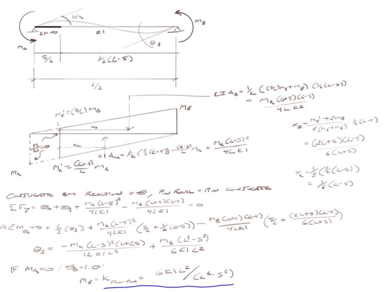
You could do slope-deflection for a fixed-pin beam loaded with a unit rotation at each end independently then solve for the Ma/Mb ratio, same process as getting K for a prismatic beam.

My Personal Open Source Structural Applications:

Open Source Structural GitHub Group:
 
Celt83, as you suggested if you take the rotational stiffness of a fixed/fixed member under a unit end rotation the stiffness is 4EI/L, for a pinned/fixed member its 3EI/L. Therefore 0.75 times the column stiffness going to one end pinned from fixed/fixed condition.

Working this assumption through in the attached for the pin end almost gets you there, but still enough of a difference to wonder if its right or wrong or a fluke?!

 
 https://files.engineering.com/getfile.aspx?folder=0e70a347-59ba-43c1-869b-94a29cfe584b&file=421.2_EXAMPLE_1_updated_calc_pages_only_again.pdf
EDIT: see my next post this is K for the wrong direction.
EDIT2: Something is wonky with the math in the screen clip, don't think it checks out. The process of getting the rotations and solving for K with the known end conditions should be right though based on a few references I have.

Here is what I get for K:
Capture_abbkri.jpg


For the carry over factor set theta,b to 0 and solve the Mb/Ma ratio.

My Personal Open Source Structural Applications:

Open Source Structural GitHub Group:
 
ah shoot my K is wrong that would be if the Column-Slab joint was pinned going from the roller to the joint. You'll need to work out theta,a and then solve for Ma assuming Mb=0 and theta,a = 1 that will give you K for proper direction.

My Personal Open Source Structural Applications:

Open Source Structural GitHub Group:
 
Cheers, yeah you're right, but that example should be enough to work through it with the one end fixed. I'll post back the solution after working through it.
 
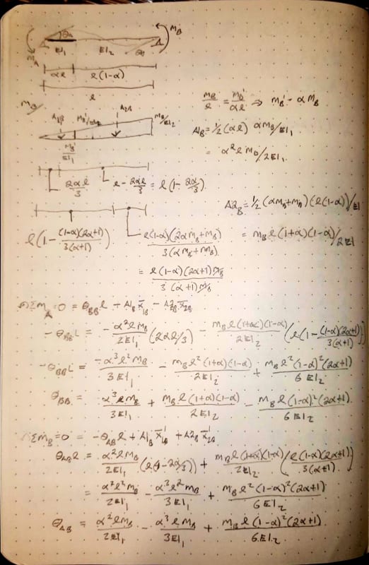
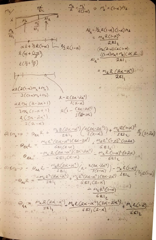
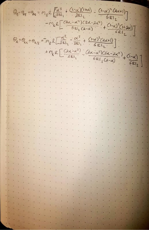
Ok kept getting tripped up trying to solve it specifically for L/2 and S/2 so did it more generally for a beam with 2 sections separated by alpha*L, checked this one with alpha=0 and 1 and get the normal formulas for prismatic beams as expected.
2020_02_10_22_53_Office_Lens_1_fldfou.jpg


2020_02_10_22_53_Office_Lens_2_ieig6x.jpg


2020_02_10_22_53_Office_Lens_3_agjj4e.jpg


My Personal Open Source Structural Applications:

Open Source Structural GitHub Group:
 
So I spent a bit of time re-looking at this yesterday. I simply could not seem to get the ACI equivalent column stiffness answer with the use of your spreadsheet Celt83.

But I did manage to determine the relationship they were using to get the 1320in^4 effective column stiffness for anyone that follows in the future.

Basically I looked at imposing in an analysis program a unit rotation at one end to both the full length pinned/pinned column with and without the half slab thickness at infinite stiffness. From this I got a moment for the two cases, this moment is proportional to the stiffness obviously.

Recognising the full length member has a rotational stiffness of η*EI/L and for a pinned/fixed member the stiffness coefficient η = 3. Then taking the ratio of the two moments and multiplying by the 3 we arrive at the modified stiffness coefficient.

We can also derive the same number as follows based on the lengths of the half column height and half height minus half the slab thickness if the half slab thickness has an I of infinity:-

i.e. η = 3*(L)^3/(L-h/2)^3

where L is the full length of the column (i.e. half the storey height in this scenario) and h = slab thickness.

Then the equivalent column stiffness is Σ Kc = Σ η*EI/(L-h/2) Σ η*EI/L


Anyone got any comments on the 2nd and 3rd questions from the original post?
 
I get very nearly the same answer at 1322.05 in^4 for Ice, the ACI example very likely has some liberal rounding. Interestingly enough if I use your definition of η I get the same result in the spreadsheet, the matching K value appears in cell P34 in the spreadsheet I posted.

Agent said:
Then the equivalent column stiffness is Σ Kc = Σ η*EI/(L-h/2)
Why are you dividing by (L-h/2) here, the length of the column is still node to node so should be L?

I recently joined the ACI 421 committee and there is an ACI conference at the end of March I'll ask some of the other committee members your remaining two questions then if they don't get answered prior. For question 2 I'd say as it is defined in the document should be 0.5*Is but I've seen several examples that also use 1.0*Is within the slab column joint.


My Personal Open Source Structural Applications:

Open Source Structural GitHub Group:
 
Status
Not open for further replies.

Part and Inventory Search

Sponsor