Continue to Site

Eng-Tips is the largest engineering community on the Internet

Intelligent Work Forums for Engineering Professionals

  • Congratulations waross on being selected by the Eng-Tips community for having the most helpful posts in the forums last week. Way to Go!

Design of Baffle Wall inside of an Inlet 3

Status
Not open for further replies.

oengineer

Structural
Apr 25, 2011
708
US
I seeking information on designing a baffle wall inside of an inlet.

My goal is to determine the required wall thickness and reinforcement for the baffle. My design intent is for the baffle wall to be a reinforced concrete wall.

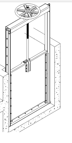
Water needs to be able to go through the baffle wall, so an opening and sluice gate are required as well for the baffle wall.

Please see attachment for image of the preliminary configuration of the wall inside the inlet:
Comments/suggestion are appreciated.
 
Replies continue below

Recommended for you

One load case to consider would be water to the top of the wall, with gate closed.
A second load case, assuming it can happen, water flowing over the top of the wall at maximum flow rate with the gate closed. In that case, assume zero pressure on the backside and calculate pressures from Bernoulli's equation on the front side.
See the rectangular plate formulas in Roark's Formulas for Stress and Strain for one approach to bending in the plate part.
It may be equally reasonable to treat as just beams running across the well.
If that is drawn to scale, it may be difficult to fit a concrete wall in while retaining adequate cover (perhaps difficult to build it, too)- consider a stainless steel plate as another option in that case.
 
Depending on how the pipe slopes on the upstream side, and what the potential flow characteristics are, you may have to consider dynamic flow pressure. If it's only 0.26% for a long reach upstream, the velocity should be fairly low. If it's steeper upstream, you may need to get a calculated flow volume and velocity from someone with experience in hydraulics, so you can calculate the loading the sluice gate and baffle wall.

Rod Smith, P.E., The artist formerly known as HotRod10
 
BridgeSmith said:
Depending on how the pipe slopes on the upstream side, and what the potential flow characteristics are, you may have to consider dynamic flow pressure. If it's only 0.26% for a long reach upstream, the velocity should be fairly low. If it's steeper upstream, you may need to get a calculated flow volume and velocity from someone with experience in hydraulics, so you can calculate the loading the sluice gate and baffle wall.

Would it be conservative to apply hydrostatic load to one side of the wall and design it that way?

JStephen said:
A second load case, assuming it can happen, water flowing over the top of the wall at maximum flow rate with the gate closed. In that case, assume zero pressure on the backside and calculate pressures from Bernoulli's equation on the front side.

If the WSE = 147.0 and the top of the wall equals EL=147.0, would it be safe to say that the water elevation would not exceed the height of the wall? Would this be the reason for needing the opening and sluice gate?
 
Would it be conservative to apply hydrostatic load to one side of the wall and design it that way?

I'm no expert on fluid dynamics, but I believe the dynamic pressure can exceed the hydrostatic if the velocity is sufficient.

Rod Smith, P.E., The artist formerly known as HotRod10
 
The thrust and overflow cases may not be necessary to be included in your design, however, it is prudent to keep them in mind when dealing with hydraulic structures. The gate might not open in time, or might not open at all, then what?
 
BridgeSmith said:
I'm no expert on fluid dynamics, but I believe the dynamic pressure can exceed the hydrostatic if the velocity is sufficient.

Would you happen to be aware of any technical guides or textbooks that would be useful in addressing the types of loading you mentioned?

retired13 said:
The thrust and overflow cases may not be necessary to be included in your design, however, it is prudent to keep them in mind when dealing with hydraulic structures. The gate might not open in time, or might not open at all, then what?

Thank you for the input.

Are you aware of any technical literature that would be useful in designing a baffle wall with an opening and sluice gate?

@everyone
Does anyone have access to any example structural details for this type of situation?

 
Would you happen to be aware of any technical guides or textbooks that would be useful in addressing the types of loading you mentioned?

No, not really. AASHTO has some equations for calculating stream pressure on a pier, but those are fairly specific to a totally different situation. Aside from that, I'm out of my depth, so to speak. I'm a structural guy who barely passed my fluid mechanics class nearly 20 years ago, and have avoided dealing with anything that flows as much as possible since.

Rod Smith, P.E., The artist formerly known as HotRod10
 
...it appears that the design of a "baffle wall" would just be the design of reinforced concrete wall subjected to water pressure.

That would seem to be pretty much it. The trick would seem to be figuring out the correct magnitude of water pressure to use.

Rod Smith, P.E., The artist formerly known as HotRod10
 
BridgeSmith said:
That would seem to be pretty much it. The trick would seem to be figuring out the correct magnitude of water pressure to use.

It would appear that if the baffle wall can resist the forces of the water at the height of the Throat Elevation, that would be sufficient. My reasoning is because the Throat Elevation would surpass the WSE and that would be the greatest water head.

Does any one have information on providing a sluice gate within a baffle wall? Any available structural details?
 
Google the words "sluice gate" you will get a lot of results. Here are two, just to have a feel.

sl_vkolbh.png


SL2_tbijz4.png
 
oengineer,

The structural aspect of baffle wall design is essentially the same as any concrete wall subject to hydrostatic pressure, but you need to pay attention to details around the opening, that will be abused by the water flow with abundant velocity head and turbulence; also, vibration from the sluice gate, albeit small, but repetitive. My only advice for you is "thickness is your friend" when dealing with hydraulic structures.

I wouldn't contemplate to design the sluice gate without consult a mechanical engineer. I think the best bet is to contact a supplier directly, if you do not have inhouse ME.
 
retired13 said:
The structural aspect of baffle wall design is essentially the same as any concrete wall subject to hydrostatic pressure, but you need to pay attention to details around the opening, that will be abused by the water flow with abundant velocity head and turbulence; also, vibration from the sluice gate, albeit small, but repetitive. My only advice for you is "thickness is your friend" when dealing with hydraulic structures.

Thank you for this input. This is what I came to the conclusion of regarding the structural design of the wall, based on my research & comments in this thread. So far, I have come up with a 10" thick wall (the wall is only 3'-2" tall, based on the sketch in the link) with vertical reinforcement of #5@ 12"o.c. At both faces of the wall.

You mentioned "thickness is your friend" when dealing with hydraulic structures. would you consider 10" thick concrete wall to be sufficient?

Would the following statement be correct:
It would appear that if the baffle wall can resist the forces of the water at the height of the Throat Elevation, that would be sufficient. My reasoning is because the Throat Elevation would surpass the WSE and that would be the greatest water head.

The Throat Elevation is 7'-6" above the top of the wall.

 
retired13 said:
I wouldn't contemplate to design the sluice gate without consult a mechanical engineer. I think the best bet is to contact a supplier directly, if you do not have inhouse ME.

Thank you for this advice.
 
I would find out from the H&H people what the flow velocity will be. My guess is that it's low.

Your flowline is at ~144' and the top of baffle wall is at 147', so that's only 3ft extra. If the flow velocity was anything material, then your sluice gate wouldn't buy you much time. My gut tells me that the hydrostatic load will be the greatest. It's only 4ft of head, so still not that much.

For your wall, I think I would start at a 10" thickness, but maybe bump it to 12".
Here are the reasons:
1) The wall could see pressure from both sides, so you need 2 curtains of steel. That automatically means you need at least an 8" thick wall.

2) The sluice gate will have anchor bolts attaching it to the wall. These might have a 6" embedment. By going to a 10" thick wall, you will have at least 4" of concrete on the far side of the anchors, and the anchor tips should not be hitting the far side rebar cage.

Other things to think about:

Junction box/manhole size - There needs to be enough room to bolt up the sluice gate. If your opening is 24" in diameter, you need room on the left and right sides to mount the gate. Absolute bare minimum is 8" extra space on each side, but I would argue for more just to make sure they can get room to drill holes, etc. It's nice to have 12"+ inches of free space around your opening. You also want room to get some continuous rebar in the wall.

What type of sluice gate will you be installing? Is it a 'self contained gate' or a 'non-self contained gate' (you should google this). A 24" gate will not weigh much, but this becomes very important on larger gates. The stem carries the load of the gate when it's opened. For a 'non-self contained' gate, that load goes straight up the stem to the top of your man-hole. This means your steel grating/platform at the top needs to be stronger. A 'self-contained' gate has a steel frame with built in beam. The gate's self weight is carried by the beam and then sent into your concrete wall. The steel grating and platform at the top of the well does not have to carry the gate weight.
 
The quote below is basically the method I used to determine the applied forces to the wall.

JStephen said:
One load case to consider would be water to the top of the wall, with gate closed.
A second load case, assuming it can happen, water flowing over the top of the wall at maximum flow rate with the gate closed.
 
JoelTXCive said:
I would find out from the H&H people what the flow velocity will be. My guess is that it's low.

Your flowline is at ~144' and the top of baffle wall is at 147', so that's only 3ft extra. If the flow velocity was anything material, then your sluice gate wouldn't buy you much time. My gut tells me that the hydrostatic load will be the greatest. It's only 4ft of head, so still not that much.

For your wall, I think I would start at a 10" thickness, but maybe bump it to 12".
Here are the reasons:
1) The wall could see pressure from both sides, so you need 2 curtains of steel. That automatically means you need at least an 8" thick wall.

2) The sluice gate will have anchor bolts attaching it to the wall. These might have a 6" embedment. By going to a 10" thick wall, you will have at least 4" of concrete on the far side of the anchors, and the anchor tips should not be hitting the far side rebar cage.

Other things to think about:

Junction box/manhole size - There needs to be enough room to bolt up the sluice gate. If your opening is 24" in diameter, you need room on the left and right sides to mount the gate. Absolute bare minimum is 8" extra space on each side, but I would argue for more just to make sure they can get room to drill holes, etc. It's nice to have 12"+ inches of free space around your opening. You also want room to get some continuous rebar in the wall.

What type of sluice gate will you be installing? Is it a 'self contained gate' or a 'non-self contained gate' (you should google this). A 24" gate will not weigh much, but this becomes very important on larger gates. The stem carries the load of the gate when it's opened. For a 'non-self contained' gate, that load goes strait up the stem to the top of your man-hole. This means your steel grating/platform at the top needs to be stronger. A 'self-contained' gate has a steel frame with built in beam. The gate's self weight is carried by the beam and then sent into your concrete wall. The steel grating and platform at the top of the well does not have to carry the gate weight.

Based on your response, it appears I am on the right track. Thank you for your comments/suggestions. As I mentioned previously, based on my calculations I have come up with a 10" thick wall (the wall is only 3'-2" tall, based on the sketch in the link) with vertical reinforcement of #5@ 12"o.c. at both faces of the wall.

I have checked the wall for a total hydro-static head of 10'-6". The top of wall is 147 ft and the throat elev is 154.5 ft. This gave me 7'-6" of water above the baffle wall. Based on your comments, my analysis method appears to be conservative. The 10" thick concrete with #5 @ 12"o.c. (each face) is adequate, structurally.

Besides the advice of "thickness is your friend", I am not sure why a 12" wall would be required, given the applied loads.

Based on your comments, a 10" wall would suffice.

Please let me know if I am missing something.
 
JoelTACive covered the wall thickness well, I am in line with his suggestion.

To the design load, I don't understand how the throat elevation related to the pipe flow, and the abbreviation WSE, so no comment at this time. But are you sure there is no chance that "surge" will occur throughout its service life? A surge will increase the pressure on the wall, and the pressure head increase is usually furnished by the hydraulist, or the pipe designer.
 
retired13 said:
JoelTACive covered the wall thickness well, I am in line with his suggestion.

To the design load, I don't understand how the throat elevation related to the pipe flow, and the abbreviation WSE, so no comment at this time. But are you sure there is no chance that "surge" will occur throughout its service life? A surge will increase the pressure on the wall, and the pressure head increase is usually furnished by the hydraulist, or the pipe designer.

I am not sure I am clear on your statement in BOLD. Are you asking what the "WSE" abbreviation is? Or are you asking about its relationship to the throat elevation?
 
Status
Not open for further replies.

Part and Inventory Search

Sponsor