Continue to Site

Eng-Tips is the largest engineering community on the Internet

Intelligent Work Forums for Engineering Professionals

  • Congratulations KootK on being selected by the Eng-Tips community for having the most helpful posts in the forums last week. Way to Go!

Channels reinf in wide flanges 1

Status
Not open for further replies.

BAGW

Structural
Jul 15, 2015
388
Hi All,

I have come across a situation where channels are welded to the web of the wide flange to reinforce the existing beam. This detail is on existing drawings and its a building that was built in 1980's. The beam is a roof purlin supporting deck and snow. Seems like it was reinforced as it was over-stressed by 15%. Maybe beam was reinforced as shown below because of site condition. I cant say why exactly.

I am re-evaluating the capacity of the composite section and I need some inputs. All members are A36 steel. I am using ASIC 360-13th edition and seems like the sections are compact. I am using section F2 to evaluate the capacity and there is around 30% increase in capacity with channel reinforcement compared to W8X10 steel alone. Is using section F2 the correct way of doing it? Also how do I calculate the weld required between the channel and the wide flange? As the CG of channel and the composite section are at the same location the equation VQ/I goes to zero.
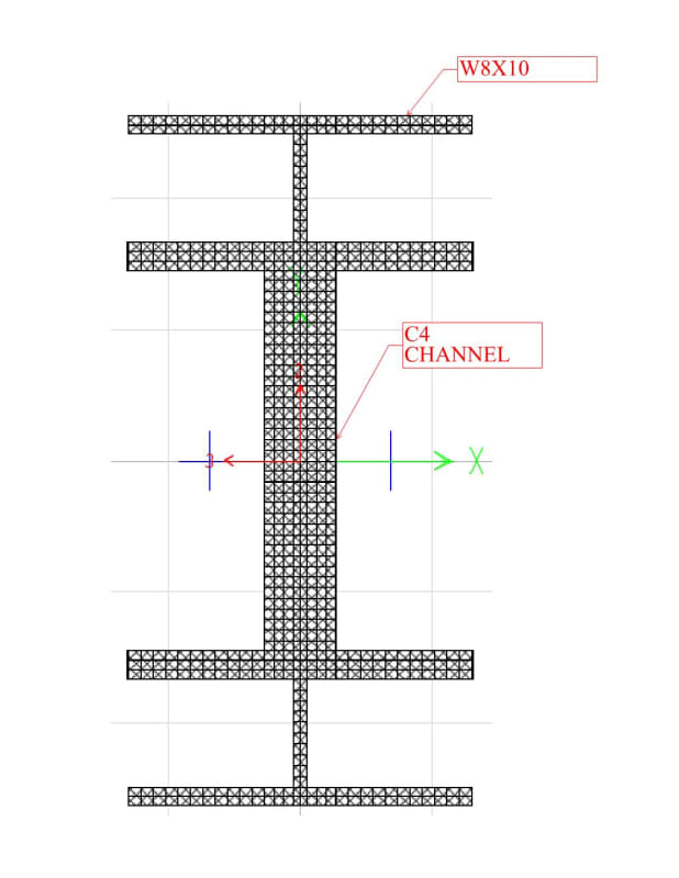
Document1_ed4bpg.jpg
 
Replies continue below

Recommended for you

I am using section F2 to evaluate the capacity and there is around 30% increase in capacity with channel reinforcement compared to W8X10 steel alone. Is using section F2 the correct way of doing it?

Me personally, I've never considered the combined properties for capacity for a built up shape. Certainly for the stresses developed.....but the capacities are a different animal.

That being said you likely could get more out of it than what I am talking about. There was a AISC article some years ago* that considered this for I-shapes with channel caps.....it definitely helped.

*='Design of Crane Runway Beam with Channel Cap', by: Ellifritt & Lue, 2nd Quarter 1998

Also how do I calculate the weld required between the channel and the wide flange? As the CG of channel and the composite section are at the same location the equation VQ/I goes to zero.

Not sure if I follow you. Q=ΣyA. "y" will most definitely not be zero.
 
Isnt the Y the distance between the centroid of channel that is used for reinf and the CG of composite section?
 
Isnt the Y the distance between the centroid of channel that is used for reinf and the CG of composite section?

In this case (i.e. to figure "Q"), the "y" would be from the centroid of the angle (created by breaking the channel in half) to the CL of the combined shape.
 
Thank you.. makes sense
 
Since the W8 and both C4s share the same centroid, the parallel axis theorem does not apply.

Moment of inertia for the composite is the sum of the 3 individual moments of inertia:
Assume C4x7.25

I[sub] composite[/sub] = 30.8 in[sup]4[/sup][sub] W8x10[/sub] + 4.59 in[sup]4[/sup][sub] C4x7.25[/sub] + 4.59 in[sup]4[/sup][sub] C4x7.25[/sub] = 40.0in[sup]4[/sup]

Distance from the centroid to the extreme fiber is unchanged at 3.95".

Section Modulus[sub] composite[/sub] = 40.0 in[sup]4[/sup] / 3.95 in =10.1 in [sup]3[/sup]

30% increase for the composite for I (for deflection) and S (for bending stress) compared to a W8x10, per OP calcs.

[idea]
 
SRE, he is trying to figure "Q" for the shear flow equation. (Which requires the "y" we are discussing.)
 
WARose, thanks, I'm confirming the OP's question:

"I am using section F2 to evaluate the capacity and there is around 30% increase in capacity with channel reinforcement compared to W8X10 steel alone. Is using section F2 the correct way of doing it?"

[idea]
 
I think there he is talking about using the combined section in the capacity equations. (I.e. LTB.) Although I could have been misinterpreting that.

Obviously there is no question that you would use the combined section properties for stress developed.
 
I see two questions, the second being:

"Also how do I calculate the weld required between the channel and the wide flange?"

Seems you are addressing the second question, while I'm covering the first. No conflict.

[idea]
 
If the load is applied to the top flange of the original W8, then all three sections will simply bend together (same delta) and the weld sizing between beam and channels is based on the load that is transferred from the top of the W8 to each channel based on their relative stiffnesses. There is no VQ/I shear flow to calculate here.

So if the channels each take 11.5% of the total load (per SRE's correct calculations above) then 11.5% of the total load must flow through the welds to get to the channel.

 
As WARose has stated, I am trying to calculate the capacity of the combined section using LTB equations of F2.. Is that not right?
 
If the load is applied to the top flange of the original W8, then all three sections will simply bend together (same delta) and the weld sizing between beam and channels is based on the load that is transferred from the top of the W8 to each channel based on their relative stiffnesses. There is no VQ/I shear flow to calculate here.

So if the channels each take 11.5% of the total load (per SRE's correct calculations above) then 11.5% of the total load must flow through the welds to get to the channel.

Interesting. I ran it the way I described above on a [similar to the subject of this thread] test problem from a old mechanics book of mine....and I came out with the right answer. But perhaps this is a good alternative.
 
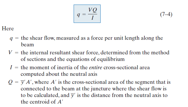
A review of shear flow equation should help.

f_hddina.png
 
WARose,
That example (7-41) is not like what the OP has here in this thread.
In all those examples (7-41 included) the section is altered such that the depth changes due to separate shapes fastened together to engage the deeper combined section.
The individual shapes have different neutral axes relative to the combined shape.
In those cases, shear flow is an issue and must be derived to determine the load in the fasteners.

For the case where you have three shapes, all with the same neutral axis and all simply bending about that axis, there really is no shear flow to worry about. VQ/I doesn't apply as I stated above.

You simply have three shapes, bending together, sharing the load based on relative stiffnesses.

 
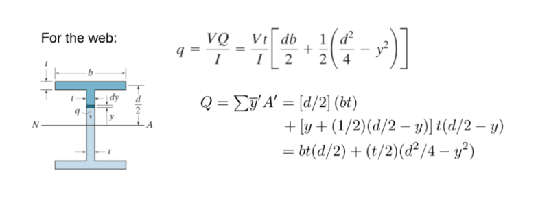
I think there are still confusions on Q and y. Here is an example, note that shear flow is calculated at a section of interest in the beam. And y is measured from the centroid of the area (above in this example) the section of interest to the neutral axis of the beam. In OP's case, the section of interest shall be located at where channel top flange intercepts the beam web, at which shear flow is to be used in weld design, if so desired.

f_wztdjo.png
 
WARose,
That example (7-41) is not like what the OP has here in this thread.
In all those examples (7-41 included) the section is altered such that the depth changes due to separate shapes fastened together to engage the deeper combined section.
The individual shapes have different neutral axes relative to the combined shape.
In those cases, shear flow is an issue and must be derived to determine the load in the fasteners.

For the case where you have three shapes, all with the same neutral axis and all simply bending about that axis, there really is no shear flow to worry about. VQ/I doesn't apply as I stated above.

You simply have three shapes, bending together, sharing the load based on relative stiffnesses.

With respect JAE, I don't agree. In the example, the neutral axis of those Tees and the web plates are in the same location.....yet there is still shear flow. I can see what you are talking about if there was a weld (or a fastener) on the neutral axis.....but with where this weld will likely fall....I don't see it.
 
Retired is correct. The equation is applicable, and will not produce zero stress, unless the sections are bolted at the neutral axis.

Ix = I.W10 + I.C4 + I.C4, since the neutral axes line up, which is not generally the case. Ix of the whole section forces the deflection equilibrium.

V = dM/dL or the slope of the moment diagram. I like to think of it in terms of change of moment per length because, then, I have built up this much moment over this much length, which I can understand.
 
Status
Not open for further replies.

Part and Inventory Search

Sponsor