Continue to Site

Eng-Tips is the largest engineering community on the Internet

Intelligent Work Forums for Engineering Professionals

  • Congratulations KootK on being selected by the Eng-Tips community for having the most helpful posts in the forums last week. Way to Go!

Anchor Bolt Design for Thrust Block Foundation Pedestal 1

Status
Not open for further replies.

oengineer

Structural
Apr 25, 2011
708
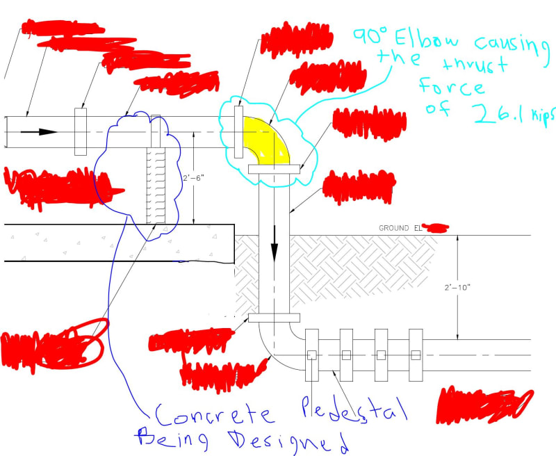
I am working on the design of a concrete pipe support pedestal. The pedestal is supporting a 16" diameter pipe. The pipe is attached to a 90 degree elbow with a pressure of 130 psi. My pipe support is located above grade.

The resultant thrust force due to the 90 degree elbow is 37 kips ( Fx =Fy = 26.1 kips [force components]). This is based on the equation in the image below:
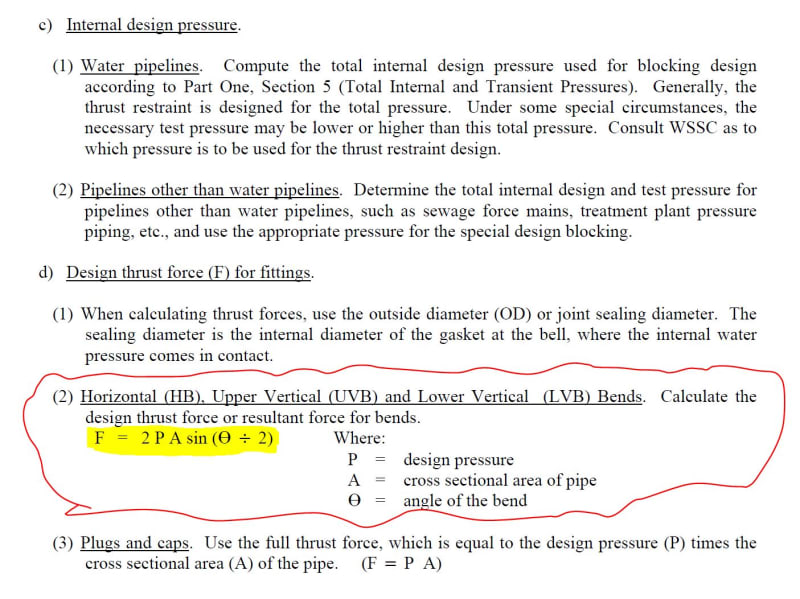
thrustblock_hjg3dt.jpg


I have obtained a sample plan sheet of thrust blocks.

See this link for the example thrust blocks:
Based on the example drawing, it seems to me as if anchor bolts are not considered when design thrust block supports. Would this be an accurate statement? Since my 16" dia pipe is above grade, would my design be under a different criteria?

The initial concrete pedestal detail that I am revising has an anchor bolt shown.
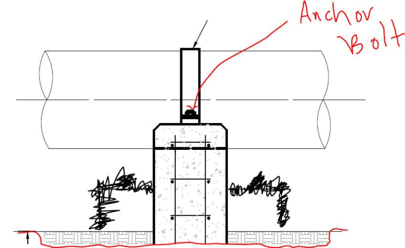
thrustblock_ancchor_cyfxm8.jpg


There are initial a total of two anchor bolts (1 on each side of the pipe) that would be resisting a horizontal force of 26.1 kips coming thru the pipe.


I initial would think that the anchor bolts need to be able to resist the thrust forces applied by the elbow ( Fx =Fy = 26.1 kips [force components]). Is this accurate?

Suggestions/comments are appreciated.
 
Replies continue below

Recommended for you

You need to talk to the pipe designer to see how the elbow is supported, and whether this support should be fixed or not.
 
retired13 said:
You need to talk to the pipe designer to see how the elbow is supported, and whether this support should be fixed or not.

I am not sure I understand what you are asking me to do?

Here is some more information of the elbow & pipe support
elbow_k0w3ah.jpg


What do you mean by if the pipe support is fixed? The concrete pedestal is cast-in-place with the slab.
 
Ask the piping engineer whether he wants to restrict the expansion and movement due to thrust. If so, it is a fixed joint, otherwise, it could be a sliding support that allows free movement of the pipe.
 
retired13 said:
Ask the piping engineer whether he wants to restrict the expansion and movement due to thrust. If so, it is a fixed joint, otherwise, it could be a sliding support that allows free movement of the pipe.

okay, thank you
 
Without some other mechanism (line stop lug, etc) on the pipe to transfer thrust load, your relying on friction to transfer that load into your support. I don't see that strap being very effective in that regard.
 
Rabbit12 said:
Without some other mechanism (line stop lug, etc) on the pipe to transfer thrust load, your relying on friction to transfer that load into your support. I don't see that strap being very effective in that regard.

Based on your statment, are you saying that the anchor bolts would not need to be designed to resist the horizontal force of 26.1 kips?
 
The strip is to hold the pipe down against uplift. The bolt fasten the strip to the pedestal.
 
retired13 said:
The strip is to hold the pipe down against uplift. The bolt fasten the strip to the pedestal.

If they are fixed supports, then the strap would have to be design to restrain the forces due to the elbow thrust, correct?
 
Which direction is your force? Parallel to the pipe or perpendicular?
 
As Rabbit12 pointed out, the strip is not capable of resisting the thrust. Note that in addition to the operation thrust (I assume), there are additional cases to be concerned with, such as startup, emergency shut down..etc. All these cases should be provided by the piping engineer. They are not up to out guess. For example on a fixed support, see "dead man" type on the thrust block detail drawing you linked to this thread.
 
oengineer said:
If they are fixed supports, then the strap would have to be design to restrain the forces due to the elbow thrust, correct?

-Vertical downward load is resisted by bearing on the concrete pedestal
-Vertical uplift is resisted by the strap & anchor bolts in tension
-Lateral load perpendicular to the pipe is resisted by some combination of bearing on the pedestal and the strap & anchors in shear (depending on how the pedestal is detailed)
-Axial load parallel to the pipe is usually resisted by welding on shear lugs (and reinforcing pads if required) to the pipe, and having those bear on the face of the pedestal
-There's no way you're going to develop enough friction between the strap and the pipe to transfer that magnitude of axial load.

The rest of the piping layout also may affect the decision of how to detail this.
 
Rabbit12 said:
Which direction is your force? Parallel to the pipe or perpendicular?

The thrust force is moving in the direction of the pipe flow (i.e. parallel to the pipe)

retired13 said:
As Rabbit12 pointed out, the strip is not capable of resisting the thrust. Note that in addition to the operation thrust (I assume), there are additional cases to be concerned with, such as startup, emergency shut down..etc. All these cases should be provided by the piping engineer. They are not up to out guess. For example on a fixed support, see "dead man" type on the thrust block detail drawing you linked to this thread.

Thank you for the advice. The civil engineer said that they would like for me to determine if the pipes need/require to be straped down. The civil engineer said that they would like for the pipes to be straped down since the elbow will cause an upward thrust force to act on it. So i think I will just go that route and design for the anchors bolts to resist the thrust force. I was told by the civil engineer that a pipe technology company can design the straps to resist the applied force, so i will not concern myself with the design of the strap. just the anchor bolts & pedestal.

strucbells said:
-Vertical downward load is resisted by bearing on the concrete pedestal
-Vertical uplift is resisted by the strap & anchor bolts in tension
-Lateral load perpendicular to the pipe is resisted by some combination of bearing on the pedestal and the strap & anchors in shear (depending on how the pedestal is detailed)
-Axial load parallel to the pipe is usually resisted by welding on shear lugs (and reinforcing pads if required) to the pipe, and having those bear on the face of the pedestal

There's no way you're going to develop enough friction between the strap and the pipe to transfer that kind of load.

The rest of the piping layout also may affect the decision of how to detail this.

I am not sure what you mean by the underlined portion in the quote?

I agree that the straps & anchor bolts need to resist the thrust force and transfer them to the concrete pedestal.
 
oengineer said:
I am not sure what you mean by the underlined portion in the quote?

I agree that the straps & anchor bolts need to resist the thrust force and transfer them to the concrete pedestal.

I think we all thought you were asking about an axial load on the horizontal run of pipe. That comment was about transferring axial load, I'll edit to make that more clear.

If you've been instructed by the pipe engineer that it's an uplift load, it doesn't apply
 
strucbells said:
I think we all thought you were asking about an axial load on the horizontal run of pipe. That comment was about transferring axial load, I'll edit to make that more clear.

If you've been instructed by the pipe engineer that it's an uplift load, it doesn't apply


The resultant thrust force due to the 90 degree elbow is 37 kips ( Fx =Fy = 26.1 kips are the force components).

This would be a vertical force of 26.1 kips and a horizontal force of 26.1 kips acting at the elbow, going parallel with the pipe.
 
The civil engineer said that they would like for the pipes to be straped down since the elbow will cause an upward thrust force to act on it.

You're contradicting yourself. You say the thrust is parallel to the pipe through the support then you post the above. I don't think you have any horizontal thrust. If you do, that strap is not adequate to resist it. As structbells alluded to, you'll need to add some lugs to transfer horizontal thrust to your concrete if you have any.

Edit, I made this post assuming the flow was right to left in your sketch. Do the dark arrows indicate direction of flow?
 
oengineer,

The linked material may offer some idea about type of pipe support. Link
 
Rabbit12 said:
I made this post assuming the flow was right to left in your sketch. Do the dark arrows indicate direction of flow?

Yes, it does. Also consider the arrows reversed. That is the direction of the flow and the thrust force.
 
I believe the formula provided in the OP are behind the design of the fittings .

The loads on the pipe supports come from another section, or more likely the folks designing the piping system and as others said must include temperature, etc and etc.
 
Oengineer, you do not mention what type piping and fittings that were used in your application and the design code. In case the piping is fully welded/flanged and you do not use expansion joint in the application the pressure is already taken by the pipe wall there is no need for pressure thrust design. However the above ground pipe may be subjected to thermal loads. In case there is not big differantial temperature to introduce axial thermal load and/or fluid excited loads I would not worry about axial thrust at all.
If I were you I would check with the piping designer for the thermal or fluid excited loads at the specific supports or ask for clarification for the issue.
 
Status
Not open for further replies.

Part and Inventory Search

Sponsor