Continue to Site

Eng-Tips is the largest engineering community on the Internet

Intelligent Work Forums for Engineering Professionals

  • Congratulations KootK on being selected by the Eng-Tips community for having the most helpful posts in the forums last week. Way to Go!

Load distribution on a Pile Cap 1

Status
Not open for further replies.

AK4S

Structural
Jan 2, 2015
98
Wanted to confirm the methodology to Analyze a pile cap to distribute the axial and lateral loads to individual piles.
Refer to the below sketch, which shows an elevated platform area with walkways connected at two locations. The platform area is to be supported by two pile caps as shown.

Generally, I would calculate the total Pile Cap loads (Axial, Lateral, Moment) about the center of the Pile Cap and provide as input for a pile-cap analysis by the Geotech engineer. The results of which would indicate the loads on individual piles.

In this particular case, the gravity loads from the walkway span are located away from the c/l of the pile cap. Due to the large eccentricity of the load, calculating the Total loads about the c/l of the Pile Cap would result in a large Moment.

[li]Would analyzing the pile cap for this condition result in high tensile loads in the piles away from the walkway area.[/li]
[li]Is this methodology representative of the actual behavior?[/li]

What happens when the pile cap is quite long and there is a heavy load at one end of the pile cap. Is calculating all loads about the c/l of the pile cap still correct to provide as an input to the geotech for their analysis of the pile group?
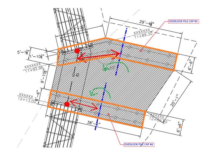
Pile_Cap_Loading_Sketch_acbmev.jpg
 
Replies continue below

Recommended for you

Can you separate the two pile caps into 4? You might need provide joint detail then.
 
@retired13: Is breaking up the pile cap necessary? how can I analyze it in the configuration shown?
I was trying to avoid a case where the pile groups would settle differently when broken up and if the corresponding joint now provided in the slab will become a trip hazard due to differential vertical movement of the adjacent slab sections.
 
I wouldn't want to do by hand. You might consider model the pile caps as foundation support on elastic spring, or simply pinned, and solve by computer.
 
AK4S said:
Generally, I would calculate the total Pile Cap loads (Axial, Lateral, Moment) about the center of the Pile Cap and provide as input for a pile-cap analysis by the Geotech engineer. The results of which would indicate the loads on individual piles.

That method works OK for simple regular structures. When things get complicated/unusual like your situation I think you need to calculate the loads in the individual piles yourself. I do not think it would be a valid assumption to assume a rig cap in this situation, and the cap flexibility will affect the load distribution to the piles.
 
@retired13 & @Retrograde: Thanks for your responses. Any advice on how I could go about calculating the loads on the individual piles, I have axial loads, lateral loads and moments in both directions acting on the pile cap.
I can only think of STAAD (from what I have at my disposal) to analyze the condition, but not able to wrap my head around on how I would apply the loads or how the load distribution to each pile will happen.
 
I would look at driving all the load into the piles nearest the application of the load. It seems to me that this is where the load is going to end up regardless of how you analyze it.

Why so many piles in such as odd arrangement? Most of them seem pretty ineffective.
 
AK4S,

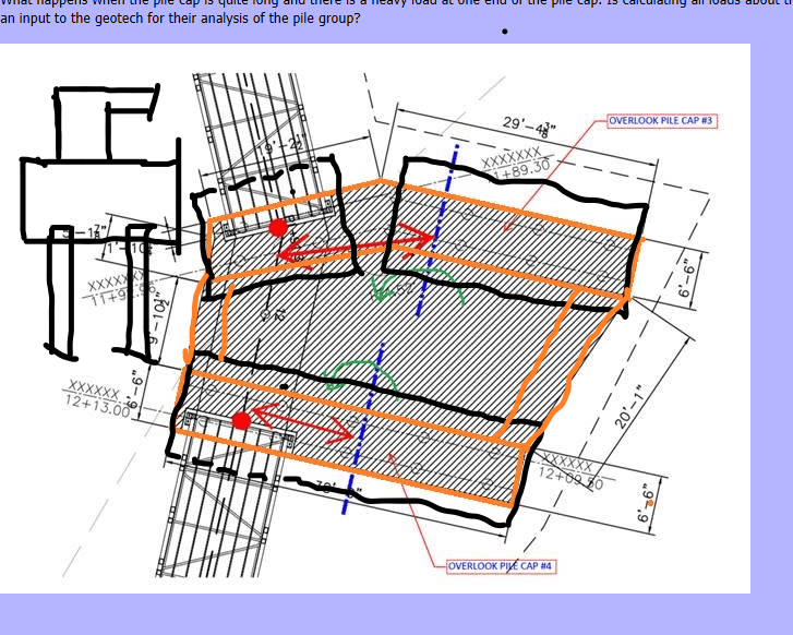
I prefer to do with 3 separated pile caps with all piles regularly arranged for ease of design/calculation. The orange lines represent grade beams above the caps to support the slab. IMO, this system is cleaner, and more stable (see sketch below).

Below outlines what I'll do with respect to your plan/layout:
1) Trail select cap thickness that equal to one half of the pile spacing, but no less than 3'.
2) Determine how many piles will be engaged to support each walkway bearing, using 45° spread from the bearing point.
3) Distribute loads to the engaged pile(s) under walkway bearing, and check shear (can be controlled either by one way, or two way action). Adjust cap thickness if necessary.
4) Make plate model with spring supports, or pin supports, and perform analysis. Note that you might run into instability problem, then you need to either revise the pile layout, add piles, or introduce grade beams to tie the caps, and provide lateral stability. You may envelop the results from the spring support and pin support assumptions to be conservative, or consider to use strut-tie method if you are familiar with it.

Let me know if I've misunderstood your plan, or left out something unclear.

b_ev6ulh.png
 
I would model the cap as a plate and model the piles as springs (pretty much as per retired13 point 4). However I would start with modeling a single cap. I would not split the cap into separate caps without first exploring the feasibility of a single cap.
 
I think you can do 3 separate caps in one computer model using links. The result will be easier to interpret. They can be combined for ease of construction though.
 
I apologize for a late response to your comments.
@retired13: Thank you for taking time to provide a detailed response. I will follow the approach mentioned, starting out with a single plate model to see the feasibility.
@Retrograde: Thanks for the response.
@JLNJ: The odd arrangement of the pile cap is to match the platform shape (shaded area) which has more uniform loads, the loads from the walkway is mainly the eccentric loading.
 
@dold: Thanks for the resource
 
Status
Not open for further replies.

Part and Inventory Search

Sponsor