Continue to Site

Eng-Tips is the largest engineering community on the Internet

Intelligent Work Forums for Engineering Professionals

  • Congratulations waross on being selected by the Eng-Tips community for having the most helpful posts in the forums last week. Way to Go!

Shear Flow of Components with Same Neutral Axis 3

Status
Not open for further replies.

Johns20188

Structural
Jan 26, 2015
14
I've been keeping up with the thread below:
There's a lot of great discussion regarding shear flow of members that share the same Neutral Axis. From the thread responses, it seems that there is no shear flow between the members that share a neutral axis.

I understand there's no shear flow for situations like a flitch beam where load is applied to all components and all components are supported independently at the ends.
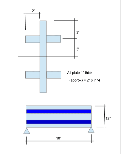
I've seen a situation where there was a simply supported wood beam that was damaged at midspan. To add strength to the beam, the engineer sistered on two 2x's, one on each side of the beam, bolted. However, the 2x's did not extend all the way to the supports. Also, the load was applied only to the beam, not the sistered 2x's. The members shared the same Neutral axis. So in this situation, is there still no shear flow? How does load get transfered to the 2xs? How do we insure that the 2xs will add strength rather than just add dead load to the main beam? Right now I'm thinking you can't just transfer vertical shear through the bolts to the 2xs because they're not supported independently at the ends.

Thanks in advance for your time.
 
Replies continue below

Recommended for you

This exactly I intended to do, a new thread for open discussion. Let me throw a hypothetic problem, to get opinions on the method/thinking in design the weld connections as shown on the sketch below.

Assume a simply supported beam with uniform load "w". Design the weld required to hold the stiffeners.
ex_piaryn.png
 
I recommend a look through this thread dealing with the interesting case of one tube concentrically placed within another tube: Link. That was my last foray into proving that there is no need for VQ/It connection when the centroids of the component members are aligned.
 
KootK,

How would you attack the problem posted above, if you are the reviewer, say the designer has specified a weld size deemed inadequate to qualify the build-up as an integral unit in resisting shear and moment?
 
I respectfully disagree that there is no shear flow, at least for the center plate. Then how the stiffeners feel the shear stress across the connecting planes? Through conformation of displacement, the stiffeners must have stress in them, my question is what is this stress, and how we calculate it by practical, or theoretical method.

I could be wrong, so I would like to see how others think about this to clear my thoughts.
 
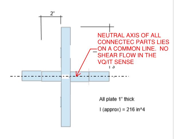
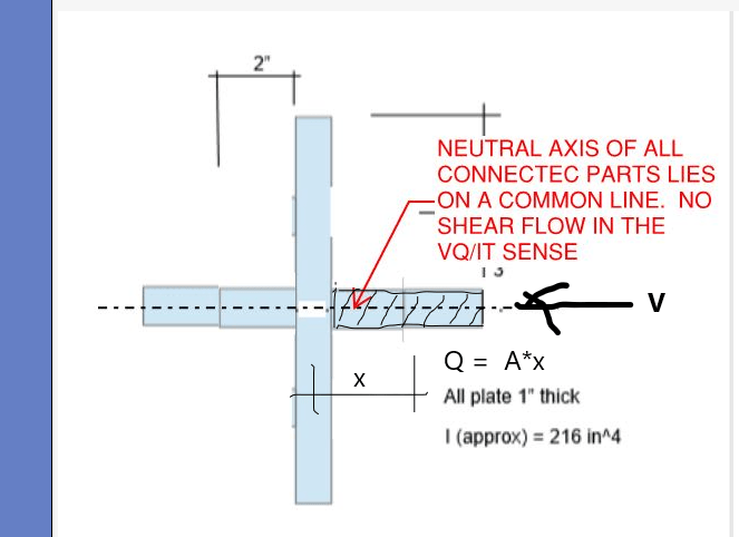
@ret13: I'm fairly certain that I'd design your example exactly as you would: classic VQ/IT. That said, your particular example is not a valid example from the perspective of this discussion because the component parts do not share a common neutral axis. Your example, rearranged to fit this discussion, would be as shown below where there would be no horizontal shear flow in the VQ/It sense.

c01_qwkdqp.jpg
 
For retired13's unrelated problem, there is not enough information to solve it, either give us the shear or the beam span so the shear can be calculated? But you solve it using the standard q=VQ/I equation like any other shear flow problem, where the area you use for determining Q is one of the out-stand plates. But this is a little off-topic from OP's question as the components are not aligned with the neutral axis.


Johns20188, I guess the designers intent was that any additional load past that already locked into the system is shared based on relative stiffness, and load is applied/transferred though the bolts. In these situations you need to resolve the end/intermediate bolt reactions back into the timber if they do not go back to the supports. This is obviously quite a tricky thing, because this reaction load changes the deformation of the timber, which in turn changes the loads shared by the sandwiched plate detail. For one way to treat aspects of partial length plates is discussed in the attached document. If in doubt take it all the way though, as noted in the conclusions. Keep it simple.

You can model this effect in a simplified way by creating vertical links between two members offset vertically. Apply the load to the timber member as it is in reality and observe the transfer of loads through the bolts (links) along the member. Design bolts (and members) accordingly. If the timber had load in it prior to adding the plates, superimpose this on the additional load applicable after it was made 'composite'.

Simply rocking up and putting some plates on the sides has very little effect, you need to unload the original members to see the full benefit of any strengthening like this. If you are dealing with a brittle material like timber, and the members already 'at it's limit' then wacking some plates on the sides does virtually nothing to improve the load carrying capacity of the system as you are still limited by the timber failing. Sure some load goes into the steel, but you'll fail the timber well before the steel takes the load it is capable of carrying due to the locked in stresses in the timber member.

 
 https://files.engineering.com/getfile.aspx?folder=86732bfd-ca91-43d1-bc01-d6417abdfafc&file=TSE_-_Flitch_Beams_With_Short_Length_Steel_Plates_-_Desai_(2002).pdf
With regard to the partial length sistering, to elaborate on Agent's stuff:

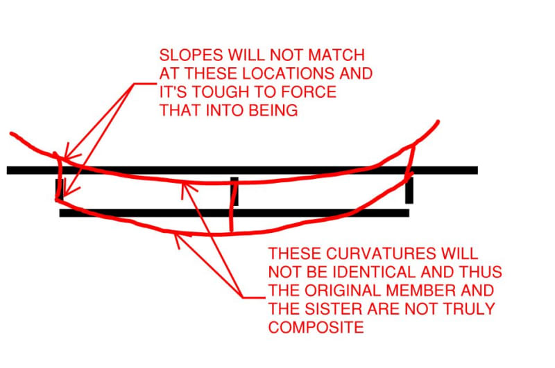
1) Without the ability to impose nearly instantaneous slopes to the ends of the sister, the member curvatures will not match along their overlapping length and, thus, the members are not technically flexurally composite.

2) To keep things simple, I'll often just model this situation as offset members connected by three rigid links and do the fasteners accordingly. Toss in some consideration of locked in stresses and jacking and I see no great benefit in getting any fancier. If it's a very long member, maybe I'll go 1/3 or 1/4 rigid links.

c01_fyw2rm.jpg
 
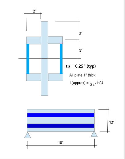
Thanks for pointing out the difference. I've revised the cross section. The span length is 10', with an uniform load "w".

ex_cquiki.png
 
Assertion from paper provided by Agent666 confirms my suspicious on the combined effect, other than shear flow alone.

.The main reason is that the end of the plate has to be connected to the timber joists at a point where shear and bending occur simultaneously.For a full-plate beam,the BM is zero at the support and the bolts carry only the steel plate share of the reaction.Moreover,there is bearing pressure exerted on timber by bolts acting in double shear.The current codes of practice on timber design do not give any recommendation to account for such combination of shear,bending and bearing.

The lack of code recommendation and academic studies are the mean reasons, that require special considerations and judgement in design built-up parts arranged in such manner - attached on sides of the mean member.
 
Johns20188, I think the there might be a terminology issue here.

Johns20188 said:
The members shared the same Neutral axis. So in this situation, is there still no shear flow? How does load get transfered to the 2xs?

Just because the weld (or bolt or whatever is fastening the components) sees stress, doesn't automatically make it shear flow. Shear flow is specifically the stress developed due to a change in bending stress along the length of the beam. Agent666 and KootK are providing good examples of how you could get load in your fasteners without it necessarily being shear flow.
 
Any comments on this connection?

v_bpx4yd.png


[Note] On the section above, the shear center coincident with geometry center, thus there is no torsion, but shear flow is non-zero. My understanding is "shear flow of a cross section is equal to zero can only occur in where V = 0".
 
retired13 said:
Thanks for pointing out the difference. I've revised the cross section. The span length is 10', with an uniform load "w".

Repeated from the other thread.

I'm with CANPRO et al on:

1) The shear flow theory that applies (or doesn't apply) here and;

2) the value of a correct theoretical understanding even if a gross, overkill approach would do.

I'll tell my story the the long way let folks pick and choose which bits they might light to challenge.

THE TWO COMPONENTS OF COMPOSITE FLEXURAL FASTENING

3) All components of the cross section must be induced, by the fastening, to assume the same curvature along their independent axes. This is usually the low demand aspect of fastening demand.

4) Where the joining of the components would increase the moment of inertia of the assembly above the sum of the separate components, the fastening must also axially extend and axially compress the component parts uniformly. This is usually the high demand part of the fastening demand as outright elongating or shortening a piece of steel really takes some doing.

THE SPECIAL CASE OF ALL COMPONENT NEUTRAL AXES BEING COINCIDENT

When this is the case, #4 is unnecessary and #3 is all that applies with respect to the fastening. This should make intuitive sense because, really, if your moment of inertia isn't going to get pushed any higher than SUM(Ix_components), why should you have to pump a ton of capacity into making that happen? You shouldn't, of course.

HOW TO FASTEN WHEN THE COMPONENT CENTROIDS ARE COINCIDENT?

It doesn't take much really. And there are two options. In step by step fashion:

1) Based on the ratio Ix_component / Ix_assembly, figure out how much load goes into each competent part. This will create a condition wherein all component parts have the same centroidal curvatures along their lengths and share a common cross section strain profile (this last bit is really what the crux of composite flexural action is).

2) Having determined the load on each component, the shear and moment diagrams for those components become determinate. They are what they are and they need to be internally consistent.

3) The problem now becomes one of imposing the requisite shear and moment diagrams from #2 on the component being fastened given that it may be that no external load is applied to the component. There are two fundamental approaches:

a) Transfer increments of shear from the assembly to the component to replicate the shear diagram that the component should have. This will result in the desired moment diagram falling into place. In this case, the welds would be designed for vertical loads only of a magnitude equal to the distributed load going to the component divided by two, applied top and bottom. This is often how we do it in wood and the fastening demand is very light except, sometimes, at reaction points, cutoffs etc where large amounts of concentrated load must be moved in or out of the component locally.

b) Transfer increments of moment from the assembly to the component to component to replicate the moment diagram that the component should have. This will result in the desired shear diagram falling into place. In this case, the top and bottom weld lines would be designed for horizontal loads only of a magnitude equal to [V/h], varying along the length of the beam [V = shear; h = distance between weld lines]. This is the method that I would favor for this application given that the path for vertical shear transfer is made a bit flexible as a result of it needing to pass through the channel flanges and induce transverse bending there.

One or the other of 3a or 3b will usually make more sense than the other based on the connection style etc. Where it's not obvious, I'll design for the worst of both cases. It's usually a pittance either way.

One could certainly be forgiven for getting the impression that #3a and #3b are both versions of "shear flow" (especially #3b). Both methods do move load around via weld shear after all. For me, the difference is that neither method attempts to impose a uniform axial strain on a component of the section which I take to be the thing that defines a classic "shear flow" problem. I suppose that another way to look at it is to say that the coincident centroids case is really just a special case of the shear flow problem in which it is possible, but not necessary, to transfer load into the component members via horizontal shear.

c02_puxtp2.jpg
 
retired13 said:
My understanding is "shear flow of a cross section is equal to zero can only occur in where V = 0".

For the cruciform condition, it becomes yet another special case in which:

1) Load sharing must be via vertical shear transfer transmitted by the welds (my 3a above).

2) Load sharing cannot be via horizontal shear transfer transmitted by the welds (my 3b above). This is because this path requires meaning separation between the weld lines.
 
Without regard to the sharing of a neutral axis, if bending occurs, then shear flow is developed when you have two different materials connected together by welding or bolting.

 
Ron said:
Without regard to the sharing of a neutral axis, if bending occurs, then shear flow is developed when you have two different materials connected together by welding or bolting.

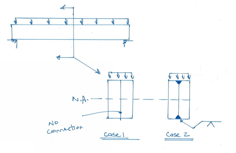
This is incorrect. See sketch below. Case 1 and Case 2 are the same size plates - the combined properties of each case are identical, the bending stress in each case is identical. There is no shear flow in the weld. The weld is not required. There might be some compressive stress in the weld due to the fact that the weld is part of the overall cross section, but the weld is not restraining two components from slipping relative to each other. There is no shear flow.

beams_y7ecp1.png
 
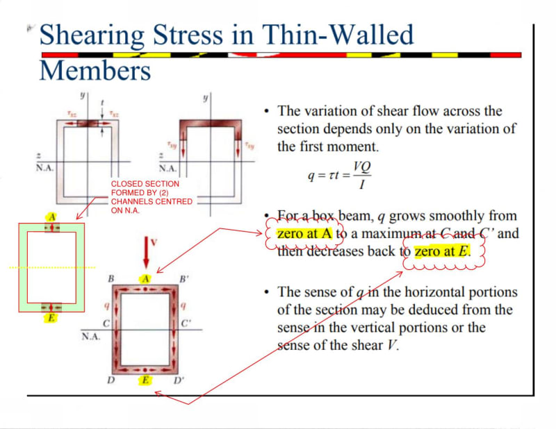
A review on shear flow on a closed hollow shape will help the understanding. Please have a look on the linked lecture. Link
 
retired13 said:
A review on shear flow on a closed hollow shape will help the understanding. Please have a look on the linked lecture.

Great link retired13, shows fairly conclusively that the shear flow is zero. If you formed your hollow section with (2) channels and welded them toe to toe, you would have zero shear flow in the welds. Same idea as my sketch above with the two side by side plates.

Scan_0006_srihm0.jpg
 
CANPRO,

Yet the picture is getting murkier when a vertical bar is placed in the middle. Because shear flow in the vertical bar will start from zero at top, then gradually increase due to increase in area, thus at the level of junction with the channel, there is shear flow in the vertical plate. I suspect the tip of the channel, upon welding, will feel the same stress. and the shear flow is simply taken as the area at the level of the top flange times distance to the NA, and divide by 2, for 2 faces in sharing the stress. I think this approach agrees with the moment gradient, so the deflected shape of the parts will conform.
 
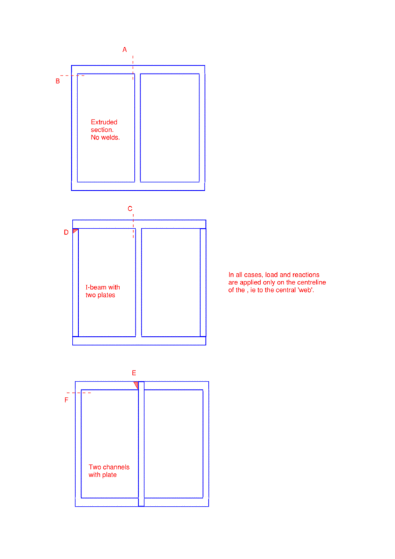
I'd like to hear thoughts (and reasoning for the differences between the three cases, if any) on which of the interfaces and notional cuts (named A-F) in the image below experience shear flow. D & E are welds, otherwise the interfaces are within an extruded/rolled section.


Shear_flow_qpdewj.gif
 
Status
Not open for further replies.

Part and Inventory Search

Sponsor