Continue to Site

Eng-Tips is the largest engineering community on the Internet

Intelligent Work Forums for Engineering Professionals

  • Congratulations KootK on being selected by the Eng-Tips community for having the most helpful posts in the forums last week. Way to Go!

Simple question in reagrd to different slab thickness 2

Status
Not open for further replies.

FreshMan2020

Structural
May 7, 2020
24
Hi Fellows,

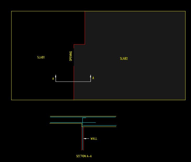
I have a question in relation to flat slab design of a job I am doing now.

I am trying to use different slab thickness for one floor
Please see my sketch below. (red lines denote walls under and external walls not shown)
SLAB_aspzm0.png


I am newbie and need your thoughts on this. Is it a common way to have different thickness for flat slab (not step down but just different thickness). If so, is the detailing above seem fine and is it a must to arrange a beam over the opening and what do I do if I don't? What else that I need to pay attention to?
Thank you.
 
Replies continue below

Recommended for you

That is conceptually fine. The bottom bars on the right side need cogs.

But I hope you have a mentor in your office who you can consult with.
 
It’s fine but the bottom bars should extend onto the wall and then cog up.
 
Thanks hokie66, Yeah, you are right, I forgot to draw the cog.
What about the opening area, If it a must to arrange a beam Or can I ignore it? I have used FEA without adding a beam and the result is fine. Not sure if I miss anything or if I need special detailing in the opening area though.
 
...and for the rest of the world outside AU/NZ, a 'cog' is a 90[sup]o[/sup] hook!
 
I don't understand the recommendation for hooking the bottom reinforcement? Anyone care to expand?
 
I would typically provide the hook on that bottom right bar but I'm not sure it is technically required by code as this is not a simple span support condition.

EZBuilding - for ACI 318 users, I believe hokie66 and others are referring to the need to develop bottom tension bars into a support.
Normally bottom bars are extended a minimum of 6" into the support per section 12.11.1 (ACI 318-11).
In section 12.11.3 there is further requirement for developing these bottom bars.
But 12.11.3 is only for simple supports and inflection points - the condition the OP presented above is neither.

There may be a different set of provisions in NZ or Australia provisions though - I don't know anything about those.

 
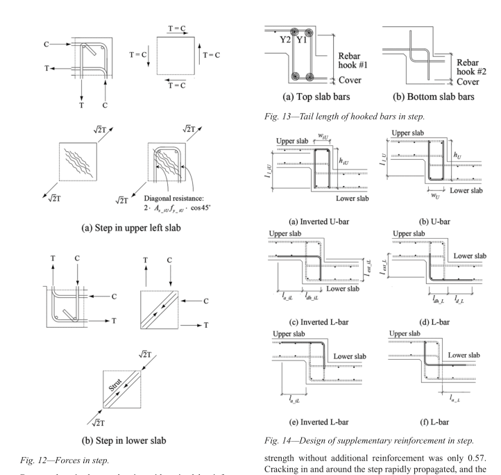
If you have an ACI membership take a peak at this reference:
Title: Reinforced Concrete One-Way Slabs with Large Steps
Author(s): Thomas H.-K. Kang, Sanghee Kim, Seongwon Hong, Geon-Ho Hong, and Hong-Gun Park

snip of general force transfer and recommended supplemental bar layout:
Capture_kbwzgt.png


My Personal Open Source Structural Applications:

Open Source Structural GitHub Group:
 
JAE - those were the exact provisions I reviewed before making a comment. Although I looked at them on ACI 318-14 because I need to start getting used to the new layout. That is a story for a different thread...

Celt83 - that is a really good reference. It is going in the database. I don't think it entirely applies here though, as it appears to primarily discuss steps along the span and not at a support.

 
Yeah I'd agree that it's not applicable in it's entirety here mainly because it's only a soffit step in a region that likely is only ever the compression face, barring any possible force reversals.

Span or support doesn't really matter I think the detailing rules established can be applied to either as long as you are paying attention to where the tension and compression faces are, span likely bottom/top and support likely top/bottom.

My Personal Open Source Structural Applications:

Open Source Structural GitHub Group:
 
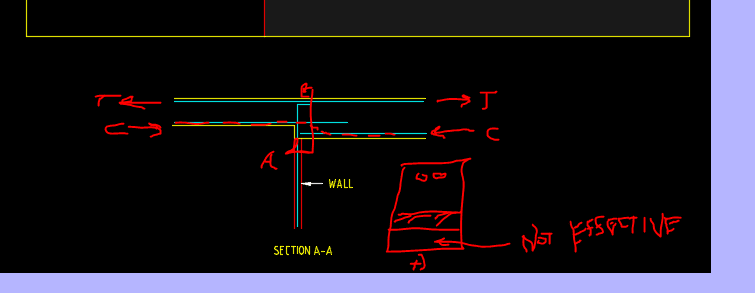
One thing I would watch out for is not designing the moment at the right face of the support using the full depth of the cross section. You will really end up with a lower effective depth of the compression block as it tries to form a strut between the higher and lower slab.

(Pardon the sloppy annotation, trying to use a mouse with the snipping tool is not a great idea)
Capture_nct6tm.png


My Personal Open Source Structural Applications:

Open Source Structural GitHub Group:
 
Celt83 - good point. The normal practice here is to extend the bottom bars (from the left hand side) into the right side some distance and only use the shallower depth "d" for the negative moment.

 
JAE:
yeah I agree that would be the normal approach, but most of the software people are using isn't built around the normal practices it is just looking at what the cross section geometry is at the design moment point. So end users need to keep stuff like this in mind.

My Personal Open Source Structural Applications:

Open Source Structural GitHub Group:
 
Celt83 said:
One thing I would watch out for is not designing the moment at the right face of the support using the full depth of the cross section.
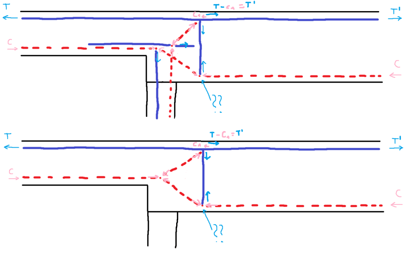
Shouldn't this also have some vertical bars at the strut bend? I drew it, hope it's clear from it (I marked the area in question with ??)
ST_vqleeu.png

I know that the upper picture is a bit complex and it's not perfect, but I wanted to show that all the reinforcement can be utilized. I think that the lower one is more elegant, as far as the drop part at least. I might be wrong, though.
 
The top reinforcement would always be controlled by the section on the left side of the wall anyway, with the lower slab depth and this reinforcement would extend to the right of the wall, so to me that is not a problem, unless it is really bad software!

 
Rapt I think those are compression struts for strut and tie not alternate rebar layouts
 
strucbells

Sorry, I misread what JAE had said. I will remove that one.
 
Status
Not open for further replies.

Part and Inventory Search

Sponsor