Navigation
Install the app
How to install the app on iOS
Follow along with the video below to see how to install our site as a web app on your home screen.
Note: This feature may not be available in some browsers.
More options
Style variation
-
Congratulations cowski on being selected by the Eng-Tips community for having the most helpful posts in the forums last week. Way to Go!
You are using an out of date browser. It may not display this or other websites correctly.
You should upgrade or use an alternative browser.
You should upgrade or use an alternative browser.
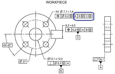
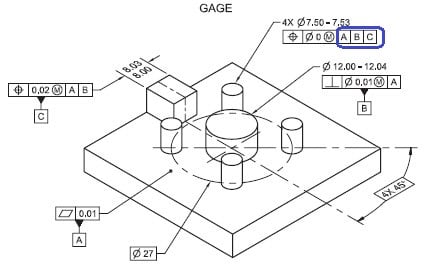
MMB at FCF on gage design 2
- Thread starter SeasonLee
- Start date
- Status
- Not open for further replies.
-
1
- #2
Season,
See section 5.2.5 on "Material Condition and Boundary Modifiers".
"This standard therefore recommends the use of RMB concept when referencing gage datum features of size. This concept allows no pattern shift on the gage as the datum features change size or become more geometrically perfect. The use of the RMB concept on datum features may cause the initial cost of the manufacture of the gage to increase. This initial increase should be offset over time by the benefits of a more accurate, reliable gauge."
Use of MMC on gauge tolerances allows for a less expensive gage while allowing for a nonzero risk of accepting out of tolerance parts. Use of MMB compounds that risk.
- Thread starter
- #3
Thanks for your comments, chez311. As for the Fig.B-6 shown below
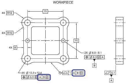
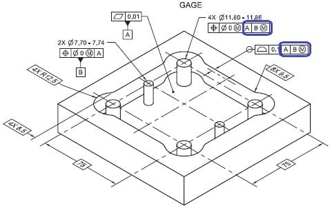
The gage FCF callout is exactly same as the workpiece(followed with MMB modifier), and what is the considerations to apply the MMB datum feature modifier here? Because of datum feature B is a two holes pattern?
Season


The gage FCF callout is exactly same as the workpiece(followed with MMB modifier), and what is the considerations to apply the MMB datum feature modifier here? Because of datum feature B is a two holes pattern?
Season
Now that I look closer at it, there are a few examples of the standard utilizing MMB on the gage tolerances. The first thing that comes to mind is that they are special cases that the tighter requirement and cost implications for RMB may not necessarily be justified.
B-6 holds a position and profile tolerance in simultaneous requirements. This is tighter than of course SEP REQT or if the profile tolerance was held to a different DRF.
B-16 includes an irregular FOS as a datum feature, arresting 5 DOF - which is significantly more complex and stringent at RMB than MMB.
B-17 has the only composite tolerance in Y14.43 (there are also no Multiple Single Segment examples). Since the lower segment holds a much tighter tolerance on the pattern relative to itself and in orientation to A (constrains both rotational DOF in both of the referenced DRFs |A| and |A|B(M)|) the use of MMB to allow some datum feature shift for the top frame of the position tolerance (which only effectively applies to location of the pattern wrt A and B) may be a justified compromise.
Or perhaps they needed a few examples of MMB utilized on the gage tolerances and chose these few special cases. I'd be interested in others opinions.
-
1
- #5
Near the beginning of paragraph 5.2.5, it states that "gaging elements that are features of size may be specified at MMC, LMC, or RFS. If referenced on the gage as datum features, they may be referenced at MMB, LMB, or RMB."
Later in the paragraph they give a recommendation of RMB, as chez311 mentioned.
Gotta love the lawyer's game of "may" vs. "shall" vs. "recommend." But in this case I think what they say makes sense.
John-Paul Belanger
Certified Sr. GD&T Professional
Geometric Learning Systems
Later in the paragraph they give a recommendation of RMB, as chez311 mentioned.
Gotta love the lawyer's game of "may" vs. "shall" vs. "recommend." But in this case I think what they say makes sense.
John-Paul Belanger
Certified Sr. GD&T Professional
Geometric Learning Systems
JP,
I agree on the distinction the standard makes on "may" vs "recommended" on gage tolerance material condition and boundary modifiers.
That said, as opposed to the simple answer to the original question (why are the datum features referenced MMB on the workpiece drawing and RMB on the gage => because the standard recommends use of RMB on gage tolerances) I was trying to determine if for the 3X examples I noted there was a particular definitive reason why there was a deviation from this recommendation, or if they were included to simply show examples where MMB "may" be used.
- Thread starter
- #7
chez311
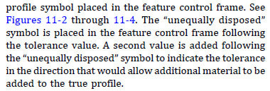
Yes, have noticed only three examples with MMB on gage FCF callout as you mentioned. I found a minor issue on Fig.B-6, the all around profile callout need to be changed to anunequally unilateral disposed profile symbol(circle U) since the standard was released at 2011, it will comply with Y14.5-2009 and looks like this:

Season
Yes, have noticed only three examples with MMB on gage FCF callout as you mentioned. I found a minor issue on Fig.B-6, the all around profile callout need to be changed to an

Season
- Thread starter
- #9
Actually... the circled U modifier is called "unequal" so your edit wasn't really needed. If all of the tolerance goes to one side then we can describe it as a unilateral tolerance, but a stickler (OK, me) would still refer to the modifier as unequal.
John-Paul Belanger
Certified Sr. GD&T Professional
Geometric Learning Systems
John-Paul Belanger
Certified Sr. GD&T Professional
Geometric Learning Systems
- Thread starter
- #11
Belanger said:the circled U modifier is called "unequal"
I thought circled U could be short for either Unequal or Unilateral, thank you for helping me correct my understanding on the symbol meaning, and it makes me find out a slight change (quotation mark added) on 2018 version to emphasize the terminology of circled U symbol.

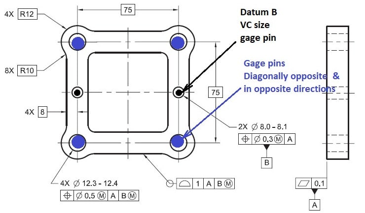
Please see the Fig. B-6 again
Let’s image one potential case when the part is placed on the gage : Datum B is VC fixed size gage pins, if the 4 holes pattern are diagonally opposite and are displaced in opposite directions within the allowed tolerance zone, the part will be locked in place even if the datum shift is available, so the datum shift tolerance will not be usable here, then what is the benefit of utilizing the MMB here?
Season
Yes, for the example you describe the four holes happen to be made in such a way that the datum shift won't be felt or used. But that's not the MMB's fault -- it's due to the hole-to-hole location.
MMB and datum shift help in regards to where the holes are relative to datum B. So if the hole-to-hole arrangement is altered a little from what you describe, then suddenly the datum shift might be very useful.
John-Paul Belanger
Certified Sr. GD&T Professional
Geometric Learning Systems
MMB and datum shift help in regards to where the holes are relative to datum B. So if the hole-to-hole arrangement is altered a little from what you describe, then suddenly the datum shift might be very useful.
John-Paul Belanger
Certified Sr. GD&T Professional
Geometric Learning Systems
Let’s image one potential case when the part is placed on the gage : Datum B is VC fixed size gage pins, if the 4 holes pattern are diagonally opposite and are displaced in opposite directions within the allowed tolerance zone, the part will be locked in place even if the datum shift is available, so the datum shift tolerance will not be usable here, then what is the benefit of utilizing the MMB here?
Specification of MMB allows some strange effects, including those that seem to violate datum precedence. Thats not to say theres no benefit - your hypothetical case is one of several that would limit datum feature shift, however most real parts will allow at least some shift. Also there are cases where the part would be fully constrained by the controlled features as you show (instead of the datum features) but you still gain the benefit of MMB - ie: if everything in your example was the same except the 2X datum features were produced shifted slightly in relation to their simulators. These would pass with a datum feature referenced MMB but not RMB, even though the part is "locked" as you say on the pattern of 4X holes.
- Status
- Not open for further replies.
Similar threads
- Replies
- 5
- Views
- 4K
- Locked
- Question
- Replies
- 16
- Views
- 3K
- Locked
- Question
- Replies
- 4
- Views
- 683
- Replies
- 2
- Views
- 1K
- Locked
- Question
- Replies
- 4
- Views
- 539

