Continue to Site

Eng-Tips is the largest engineering community on the Internet

Intelligent Work Forums for Engineering Professionals

  • Congratulations GregLocock on being selected by the Eng-Tips community for having the most helpful posts in the forums last week. Way to Go!

Wind Load applied on timber roof

Status
Not open for further replies.

Aleeeex

Civil/Environmental
Aug 14, 2020
42
Hi Guys,
This is my first time posting here! I am in need of your help! I just finished my degree and I was wondering if you can possibly give me some guidance, I am practicing calcs on residential timber properties. I applied the uplift wind load on the roof at the Gable side where there are 6 columns however I am not sure how can I distribute the load on the gable beam as the roof is diaphragmed. Please take a look at my sketch and please share your thoughts! I need to find the axial forces, reactions uplift on these timber columns.
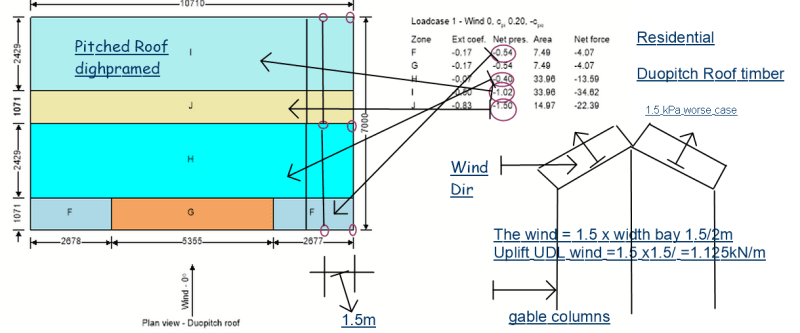
image_lshsza.png


Thank you in advance
 
Replies continue below

Recommended for you

The diaphragm doesn't come into play when talking about straight up wind uplift besides stability. The wind uplift will apply distributed loads to your edge beams and ridge beams. Those uplift distributed loads will cause uplift on the columns if there isn't enough dead load to hold the beam down.

Now, as a new designer they may have mentioned these things in school, but they generally don't give you enough exposure to it in a practical sense. Figure out your lateral system first. The roof diaphragm is the first step, but how does that diaphragm load get down to the ground? Shearwalls? Cross-bracing? That answer is equally important as the gravity (or uplift) design of the beams and columns. In fact, it's more important.

 
Thank you for your reply!

So how I distributed the load on the beam is correct half of the bay. I also got 1 KPa dead load and 0.75Kpa snow load. I should add them in my combinations.

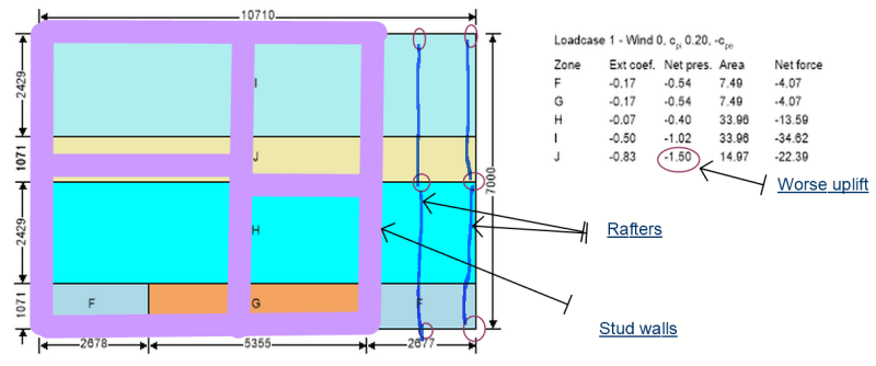
I have stud walls as showing in my sketch, that is how diaphragm load get down to the ground?

image_fsz4vs.png
 
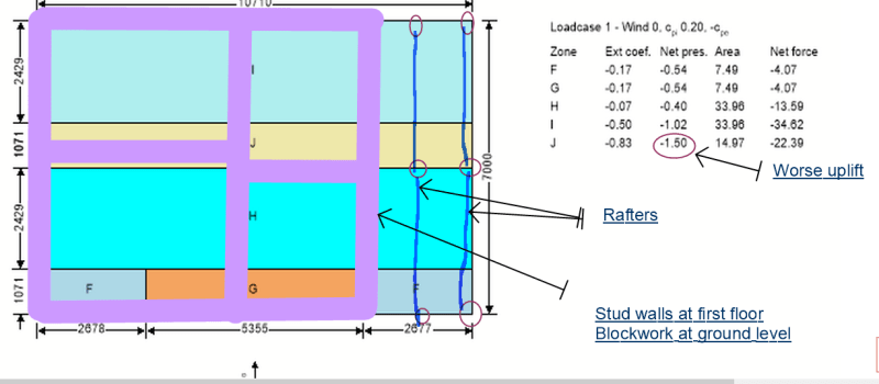
I got stud walls at first wall and cavity walls at the ground level.

image_hvm7uj.png
 
Yes generally speaking the lateral wind load is resisted by the stud walls, but they must be detailed as shear walls. There should be plenty of literature available for you to design to your local code.

It does appear you're attributing the loading correctly. That seems like a lot of columns for only 2.7m I feel that you could likely get away with just 3 columns and design your beams to span the 2.7m, that's not out of the realm of normal for a beam span. In fact, two columns only 1.5m apart seems oddly close.
 
Thank you Jay,

I will have a look at stud walls details. I also might get rid off other 3 columns.

One more question, when designing the ridge beam and rafters every 400mm spacing, do you consider the wind load as well? or dead and imposed load only?

I got maximum ridge span around 5m with cross loading width of 3.5 m , so the dead and imposed load applied = 1kpa x 3.5 x 1.4 +0.75Kpa x 3.5 x 1.6.

If I need to consider the wind load as well on the ridge beam would be 1.5Kpa x 3.5m =5 kN/m? Is that correct?

Thank you for your patience.

 
Do you apply the wind load on edge beams times the rafter spacing or half the spacing between the columns!

I mean instead of 1.5kPa uplift times 1.5m/2 is just 0.4m/2 for the edge beams and 1.5kpa x 0.4m for the beams in middle.
 
Think about load path from the roof to the ground - tributary roof panel load -> purlins (if present) -> rafter -> ridge beam and edge beam -> walls/columns. The columns are usually required for strength and stability, especially for wind normal to the wall.
 
So when I need to design the edge beam on the gable side, is the wind load KPa times the spacing between the rafters? or the spacing between the columns?
 
The rafter will carry the load between the two adjacent rafters (tributary width = spacing of rafters), then the reactions at the end of rafter become applied load to the ridge and edge beams. The ridge and edge beams will be supported by columns/walls, and design for the loads.
 
Status
Not open for further replies.

Part and Inventory Search

Sponsor