Continue to Site

Eng-Tips is the largest engineering community on the Internet

Intelligent Work Forums for Engineering Professionals

  • Congratulations KootK on being selected by the Eng-Tips community for having the most helpful posts in the forums last week. Way to Go!

Dimensions for a Helicoil Gauge

Status
Not open for further replies.

StarSight

Aerospace
Aug 14, 2020
3
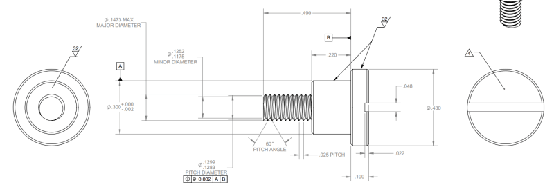
I'm trying to dimension a part that is supposed to screw into a hole that has been tapped for a 4-40 helicoil. This would be BEFORE the helicoil is inserted, kind of like a STI Go/No-Go gauge. I haven't been able to find any example drawings of those gauges though. I've always been able to use standard thread callouts before, but I haven't specified custom threads like this. My understanding is that a helicoil tap just has a greater major diameter than the standard thread. This is what I have created so far.... is this adequate? What else should I be doing? Thanks in advance!
helicoil_gauge_ynsv58.png
 
Replies continue below

Recommended for you

StarSight,

It has been a while since I have played with thread gauges. As you hopefully know, go[ ]gauges test all features of the part, and no[‑]go[ ]gauges test one feature only. Thread no[‑]go[ ]gauges generally test the pitch diameter.

A crude rule of thumb is that your gauge must be ten times as accurate as the feature being measured. I don't have helical thread insert specifications here. A 4[‑]40UNC internal 2B thread pitch diameter is .0991/.0958, so a no[‑]gauge for this must be accurate to [±].00016". You need to be able to be able to fabricate this and inspect it.

Why would you not just buy a helicoil insert thread gauge?

--
JHG
 
Is this a thread gage? The tolerance on the .3" Ø makes me think not.

Or was the larger-than-4- thread ( costly, unique ) size chosen over an 6- or 8- thread for security or a hopeful effort to guarantee sales of replacement parts ? or some other reason?
 
Thank you for all your responses so far. Unfortunately, this is not a thread gage. This is to locate a copper coil for precise bonding to a housing. The tight 0.3" OD serves as the radial locating feature constraining in x and y. The 0.43" head constrains z. Once the coil is done bonding many days later, the tool is removed. The hole in the housing is a through hole tapped for a 4-40 helicoil insert, but the insert is for a part on the other side of the housing. I'm trying to use the hole that already exists for locating without having to put an insert in just because I don't know how to dimension a gage! haha
 
I think you need more than one ?

Does the tool(s) HAVE to be left in place?
Must the bonding adhesive be kept out of 0.3"Ø zone?

I'd buy X number of Helicoil taps. $20 US Bucks - I'd make a bunch of 0.3" Ø plugs and, with the same setup used to turn the OD ( to ensure concentricity), tap a hole in the center with the heli-coil tap.
I'd loctite the plug to the helicoil tap.
I'd spray these guide assemblies with mold release suitable for the adhesive used to bond the copper coil, and install the guide assemblies in the assembly to be bonded.
Maybe it would make more sense to machine the plugs out of Teflon, or ???, and taper the OD a few 0.001 inches, to be gently installed after the copper coil is set in position


When the copper coil does not fit due to positional variations of holes in the coil, and the tapped holes in the main thing, I would mill flats on the sides of a few (but not all) of the guide assemblies, and install them oriented to permit them to adjust to the holes in the copper coil.
 
Status
Not open for further replies.

Part and Inventory Search

Sponsor