Continue to Site

Eng-Tips is the largest engineering community on the Internet

Intelligent Work Forums for Engineering Professionals

  • Congratulations KootK on being selected by the Eng-Tips community for having the most helpful posts in the forums last week. Way to Go!

Base Plate Stiffners 3

Status
Not open for further replies.

Arun4567777

Structural
Aug 11, 2020
87
Hi Guys!
I am designing Base Plate as per AISC Design Guide 1 with large moment case.
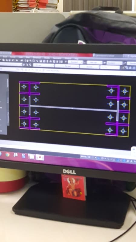
In Bearing the the cantilever bending distance is m or n .What will be the effect if I use stiffners.
I have using 8 bolts per flange.
 
Replies continue below

Recommended for you

IMG-20200822-WA0006_ssn48f.jpg
 
I think the method for base plate design case with m and n dimensions is mainly for concentrically loaded column, or with small eccentricities. For large moment with resultant force fall outside of the kern, you should use other methods.

For the monitor stand, the moment/rotation is countered and balanced by the weight and large contact area of the seat pad. Unless you want to design it for the earthquake case.
 
How thick would your baseplate be if you had no stiffeners? Maybe less costly?

Dik
 
That's bananas! Not sure what your situation is so I'll just give my armageddon outlook:

1. Lots of welding distortion at every T-joint of the stiffener
2. Plate is going to get punished with all the stiffener welding
3. Welders will be cursing you for the tight access
4. Ironworker will be cursing you for the bolt access


Look into Blodgett's book and he shows an analysis case for stiffeners. I also think there may be some illustrations that could give you a few alternate designs. Good luck.
 
What does your compression block look like? I imagine it's centered under the flange so that all you have is the plate spanning in a three-sided manner between the stiffeners/flange. Pretty simple to analyze.

For the tension design, I would expect bolts such as these to sit up on chairs. This gives you better weld access, more length for the axial tension to be transmitted, and a length of bolt to pretension if the design demands it. The top plate can then simple span between stiffeners as a one-way element.

Having the outside bolts so far outside the beam section makes the flange work very hard in the cross direction. I'm not a fan of this arrangement.
 
@all
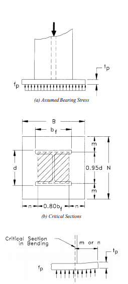
As per AISC the m and n distance is measured from the center of flange to the edge of the Base Plate.Sinve I am using stiffners what will be the value of m and n ?
If I am ignoring the stiffners my Base Plate thickness comes around 50 mm which will result in more weight.For tension I know how to distribute the forces.I am just confused for bearing.
 
Sammy345 said:
If I am ignoring the stiffners my Base Plate thickness comes around 50 mm which will result in more weight.
Any why is that a bad thing? Weight shouldn't be the metric you should be focusing on.
 
In general a thicker plate is preferable to stiffeners, but sometimes you need then.

In my opinion your detail has too many stiffeners.
 
I don’t believe the method in the Design Guide is appropriate for your base plate. Why are you using it?

If you provide better information you will get better answers. What are your axial loads and moments?
 
Thanks Skeletron... my thoughts exactly; it's very seldom that I add stiffeners to base plates. The 2" base plate would be a lot easier and far less costly, IMHO.

Dik
 
As per AISC the m and n distance is measured from the center of flange to the edge of the Base Plate.Sinve I am using stiffners what will be the value of m and n ?
If I am ignoring the stiffners my Base Plate thickness comes around 50 mm which will result in more weight.For tension I know how to distribute the forces.I am just confused for bearing.
There is no "m" and "n" for this case.

On the tension side, you can use yield line theory to determine the required plate thickness. Maybe that thickness will be pretty high, considering this is a large moment case, and "ok by inspection" can be used on the compression side. For example, if the thickness is half the clear distance between stiffeners, then it's not really a bending problem.

Unless an unstiffened design results in an absolutely enormous thickness, I'm with all the guys here who are saying there are too many stiffeners. Stiffeners are so much more expensive, I would only resort to them if that's the only way to make the connection work.
 
In my case it is necessary to use them as I would be ultimately saving if I do this. I also don't prefer using stiffners but this time I have to use them.
Btw I found a procedure on how to do it.I will understand the principle and update you guys
 
Sammy,

Can you provide the proposed baseplate layout with column stiffeners shown? We are shooting in the dark, so far.
 

Why do you have to? If for no other reason than a cost savings?

Dik
 
In my case it is necessary to use them as I would be ultimately saving if I do this. I also don't prefer using stiffners but this time I have to use them.
Now I'm curious. How could all the extra fabrication possibly result in a lower cost compared to even a 2x thicker plate? Do you have a source of slave labor? LOL.
 
You can't use DG 1 without adjustments/modifications on equations and design parameters. Try this paper, see if it fits your need. Link
 
AISC DG 1 said:
Base Plates with Moments
Base plates with both axial loads and moments are not covered in the AISC Specification or the Manual of Steel
Construction. Engineers must refer to textbooks for design information, though not all texts cover this case.
Two general approaches exist for design, one based on the elastic behavior and one based on the ultimate
capacity. For each of these approaches, different assumptions are made.

 
You have to evaluate the stress distribution under the column within the area covered by the stiffeners. Other concept is similar to DG 1, as shown below, to get the plate thickness.

image_yu0x8r.png
 
Status
Not open for further replies.

Part and Inventory Search

Sponsor