Continue to Site

Eng-Tips is the largest engineering community on the Internet

Intelligent Work Forums for Engineering Professionals

  • Congratulations waross on being selected by the Eng-Tips community for having the most helpful posts in the forums last week. Way to Go!

Embankment flow net and heave

Status
Not open for further replies.

Fynch

Civil/Environmental
Apr 16, 2020
25
GB
Hello,

I'm trying to calculate the piping FoS and heave from a flow net.

I've attached the below but it was a quick sketch just to lay it out (please ignore scales/accuracy etc. - I did this for the purpose of this question). There's no sheet pile or toe in the embankment, though the embankment will be keyed in by 300mm. Embankment footing is about 4m in length. Unit weight = 20kn/m3. 1.5m from GL to impermeable layer.

1) I believe with regards to piping - I need to measure my last "square". However, as you can see - I appear to have done something wrong with my last square. Would love to know what I've done if anyone has suggestions (may be to do with not including the keyed in section?)

2) I really am lost with the heave calculation. I have an old uni note to say the width is 0.5d. However, I can only find examples of d with regards to sheet piles (depth to bottom of sheet pile) - I don't understand how to do this with an embankment. Also I've seen equations to calculate i but again - I'm lost as to whether you calculate this using d (depth) or l(length i.e. 4m).

Apologies if this is obvious - it's been a long time since I even looked at this stuff and doesn't seem as obvious as it once did. Anything anyone has to explain this to me would be very much appreciated.

Thanks in advance
 
 https://files.engineering.com/getfile.aspx?folder=76ec3bdb-ddb6-4c0a-be32-2c13648d6c5e&file=flow_net_sketch.jpg&__hstc=212727627.58811099112d43f44e7012aee5915c53.1601486436703.1601589999624.1601811714971.4&__hssc=212727627.21.1601811714971&__hsfp=2495728706
Replies continue below

Recommended for you

However, as you can see...

No. We couldn't see. Can you spell out your problem directly, instead of asking everybody to guess.
 
Maybe my background is a little ancient, but in these situations, heave never entered the picture. The head drop in that last "square" was the main thing to evaluate. Probably the same thing.
 
Okay - so I've taken a look at that guidance (albeit it says the flow net is a poor example), and I have re-adjusted my squares. Does this seem about right? (attached).

It appears I'm not having a lot of luck with part 2 of my question about heave... Oldestguy - how come heave never entered the picture?

Thanks,
 
 https://files.engineering.com/getfile.aspx?folder=d76e45ea-c3a1-45d9-9550-f10cb1a22658&file=flow_net_2.jpg
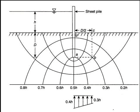
The heave piping can occur on the downstream side of a sheet pile, or seepage cutoff wall, when the built-up of upward hydraulic pressure at the toe exceeds the weight of submerged soil. As per Terzaghi, the critical heave distance is D/2 from the down stream face of the cutoff wall, of which D is the sheet pile/cutoff wall embedment length. In your case, where is the built-up of pressure differential required to cause heave? nk again.

image_fctqrj.png


In Fig., the equipotential line of 0.4h potential head passes through point a, and that of 0.3h potential passes through b. Hence, the average hydraulic pressure on the base ab of the prism abed is –

image_kjmnul.png


Upward seepage force per meter length of the wall is –

image_acbhdm.png


Downward force due to the submerged weight of the soil is –

image_te6cus.png


Heave piping would occur when Fs > W. The factor of safety against heave piping can be obtained as –

image_mbmxpa.png


where ϒ' is weight of the submerged soil, and hab is the average hydraulic head for a distance of D/2 from the downstream end of the sheet pile..
 
This is the thing - I'm not sure where D is in relation to my example as I have no seepage cut off. The flow path is impacted by length it is travelling under the embankment only.

This is why I didn't know if I should consider D to be the length of the embankment footing, or the keyed in depth. Or neither
 
IMO, D = 0 in your example for flat bottom embankment. The potential of heave is right at the downstream toe (the last square).
 
I would think that the dam must have some embedment below the ground surface, both upstream and downstream. I can't imagine that someone built a dam directly bearing on the ground surface and then filled the lake.

The top flow path in the latest flow net still has no way for the water to enter or exit the flow path. Re-draw the flow lines.

 
to PEinc. If the friction capabilities of soil below the dam are sufficient thee is no need for embodiment. Main risk is erosion starting at the outlet of the water. Of the dam failures reported that I can recall,none are due to dam slippage, etc.
 
Fynch,

I guess you are overthinking on this matter. For your case, you have a (say) uniform head under the embankment, that is r[sub]w[/sub]*ΔH; at the downstream toe, you have a varying soil pressure of r[sub]s[/sub]*h[sub]s[/sub] going upstream. Heave will initiate at where ever r[sub]w[/sub]*ΔH exceeds r[sub]s[/sub]*h[sub]s[/sub], so that's why a zone near the downstream toe needs to be protect by impermeable blanket, or a key to reduce the upward pressure. Hope this makes sense to you.
 
Status
Not open for further replies.

Part and Inventory Search

Sponsor