Eng-Tips is the largest engineering community on the Internet

Intelligent Work Forums for Engineering Professionals

Beam Over Column Connection 1

Status
Not open for further replies.

Veer007

Civil/Environmental
Sep 7, 2016
379
0
0
IN
Hey Guys,

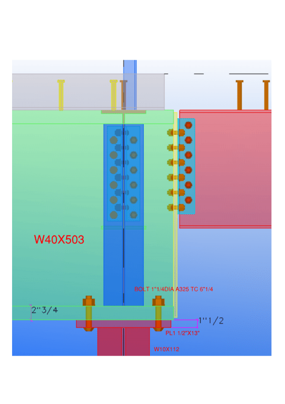
I have the case, where beam bearing on column cap plate which has 360kips as shear and no moment force. Shear force will be satisfied by using direct bearing. Is this necessary to design cap plate thickness and number of bolts still? If yes any way to design? Or just I need to provide cap plate thickness same as beam flange?

below from AISC (Hollow StructuralSection Connections) states cap plate thickness should be min of beam flange.

[highlight #EF2929]"The following is a simplified check provided in Part 9 of the AISC Manual based upon the “no prying action” equation.
Because tmin < tf , there is no prying action in the beam flange."[/highlight]

Capture_s3kkeb.png


Beam flange thickness is 2.75"

Document1_l16pij.png


Thanks in advance!!
 
Replies continue below

Recommended for you

Well somebody needs to design it and if you don't somebody else may and get it wrong. Also you should recognise that there will be some moment transferred. Your bearing connection will have a non insignificant amount of stiffness to it. My preferred approach is to model the connection as both a moment and a pinned connection and see if the column passes. If it fails with a moment connection you need to design you connection to behave in a clearly flexible manner.

For starters if you want it to behave more like a pinned connection shrink that cap plate to slightly less than the flange width and bring the bolts well into the center.
 
If the connection is a pin is it still stable? That might give you some idea about what forces you might need to be designing it for.

If continuity is required to maintain stability, then design as if the beam and column are continuous. Take 2.5% of the axial load and apply it at bottom flange level acting sideways treating the column and beam as a virtual continuous vertical member, then design the connection and stiffeners to resist the moment generated. Often the axial load clamps it together and bending is minor.

Given you have the column with web not aligning with beam web, there are some localised bearing checks that might be required. Unclear what your stiffener arrangement is based on your view.
 
Agent666 said:
Given you have the column with web not aligning with beam web, there are some localised bearing checks that might be required. Unclear what your stiffener arrangement is based on your view.
Its WT of W10X45 stiffener

Thanks in advance!!
 
Try this, some of the concepts I was discussing are embodied in the advice starting on pg12 regarding stability of spine beams. A few pages in it discusses the method and concerns around columns under continuous beams.
 

From table 5-1 AISC stated axial tension for W40X503 under yielding is 6660 kips, if I take 2.5% which is 166.5 kips load. Can I consider bolts in axial tension? so that from table 7-2 states 1 1/4"Ø bolts takes 82.8 kips (166.5/82.8=2 bolts), which is fine?

Cap late yielding capacity 0.9*Ag*fy=0.9(1.5*13)36=631 kips>166.5 kips

What my concern is 2.5"flange thick has high bearing stress, so 1.5" plate thick will be fine?

Thanks in advance!!
 
1) You should design the cap plate as a flipped column base plate to resist the bearing stress from the W40x beam.
2) Don't you have horizontal shear force on the connection? It seems the 360 kips is the vertical reaction, is it?
 
no, horizontal force were given, yeah its shear 360kips.

And I'll take into account that 2.5% axial tension act on beam as Agent666 states.

Thanks in advance!!
 
Thanks r13, I'll try.. do I consider bolts tension as anchor rod tension instead in the calculation?

Thanks in advance!!
 
Even better, here is a copy of AISC DG #1. You can directly jump into section 3.1.2 (p15), and assume an uniform pressure, f[sub]P[/sub], equals to the beam end reaction divide by the area of the cap plate, then complete the steps that follows. Link


Did you consider the stability of beam W 40 X 503 during erection?

I would prefer to extend the column W 10 X 112 and make soffit with the top level of beam and make connections with web angles..
 
Doesn't it better column stops below beam? framing with side of column may create eccentricity.. right?

Thanks in advance!!
 

It is not a good idea to stop column below the beam. The proposed detail will create more eccentricity for the column. You may assume the beam simply supported on the bottom flange but, the same is not true for the column. Compare the stiffness of W 40 X 503 with the weak axis of the column W 10 X 112. The column could be assumed rigid connected to the beam.

Regarding your statement 1;

The assumption of no moment force for the beam is conservatively true.. what about the pink painted beam ( could be W 24..? ). Still the beam W 40 X 503 could be assumed simply supported and no moment will develop. However, the column will experience almost the rigid connection moment which will be higher than connections with web angles.

It should not be so time consuming... Just run two alternatives:

1= The beam rigid connected to column and pink colored beam
2= The beam (s) connected to column with web angles with eccentricity. (the modelling of ecc. for W 40 X 503 , for the weak axis of the column W 10 X 112 should be around 1/2 in.)

..and see the situation.
 
Veer007,

Your design is acceptable, but HTURKAK's approach is more conventional and stable, consider the lateral displacement potential. I guess your task is to provide details for the connection, while the design was done by others. Correct me, if I am wrong. The moment on the connection may not be significant, but it is there, not to mention the 360 kips load can be off center too. Did you consider minimum eccentricity in the design?

image_lykjfw.png
 
I've done it both ways... and if I can, I use continuous construction with the beam running over the column.

Rather than think climate change and the corona virus as science, think of it as the wrath of God. Feel any better?
-Dik
 
Either way has its merit, however, I pay more attention to relative rigidity between the connected members. The aspect ratio (Beam-column) of this case somewhat beyond my liking, but acceptable.
 
Status
Not open for further replies.
Back
Top