Eng-Tips is the largest engineering community on the Internet

Intelligent Work Forums for Engineering Professionals

  • Congratulations waross on being selected by the Eng-Tips community for having the most helpful posts in the forums last week. Way to Go!

bracing working point 5

Status
Not open for further replies.

wrxsti

Structural
Sep 18, 2020
196
JM
if i design a bracing with working point at top of baseplate where no eccentricity to be considered

and then a 6" slab is poured covering 6" on top of baseplates

what effect does this have?

also in a redesign

could i consider this 6" above baseplate

a new working point without eccentricity consideration
 
Replies continue below

Recommended for you

*no effect.
*the new working point does not change the fact that there is an eccentricity, but the slab may absorb some of the moment.

BA
 
The joint will only be concentric if the line of connection shear resistance passes through the work point. If you mean for the slab itself to provide the shear resistance at the connection than, accordingly, both of these conditions will result in some eccentricity in the joint:

1) Work point at the base plate.

2) Work point at the top of the slab.

One might put the work point at the mid-depth of the slab to try to iron out the eccentricity. However, it's often difficult to know where within the slab the center of connection shear resistance will be located.

Can you share a sketch of your proposed connection detail?

 
Unless the loads are significant, I normally don't concern myself with this.

Rather than think climate change and the corona virus as science, think of it as the wrath of God. Feel any better?

-Dik
 
march8th_i8cv7j.jpg


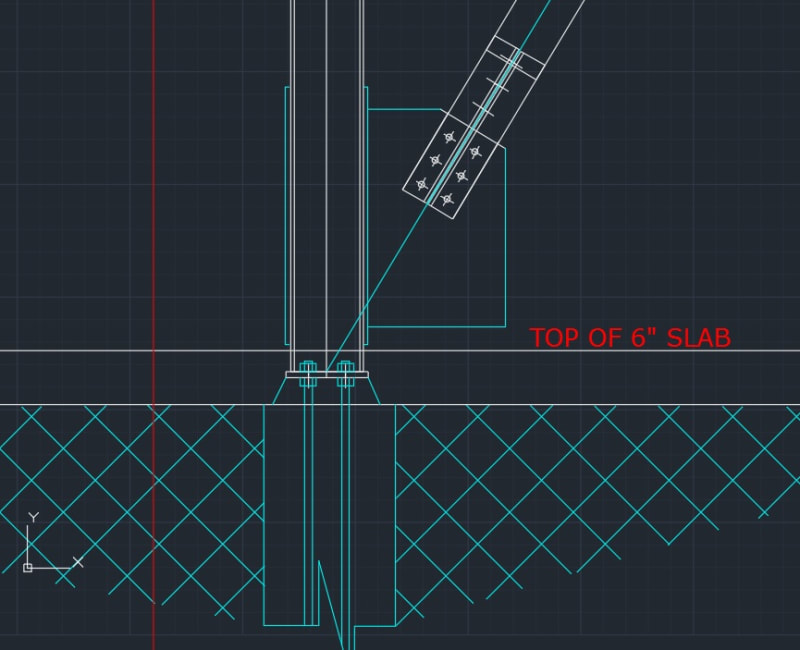
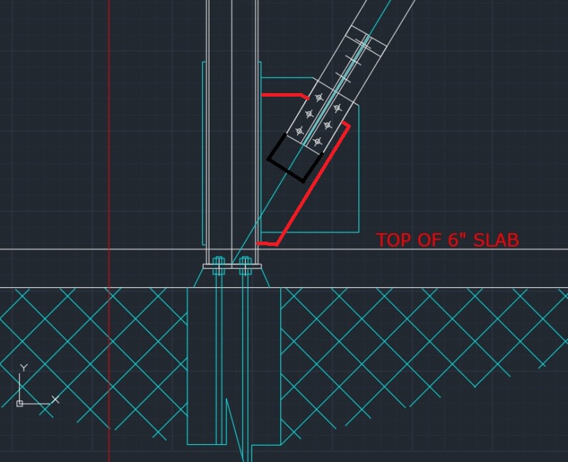
column and slab is existing in configuration as shown
i want to install new brace as shown

with field measurement im getting slab about 3inches above top of bp
 
my real issue is this one below

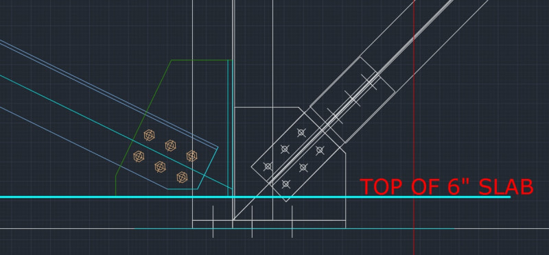
march8th_2_ktfsvl.jpg


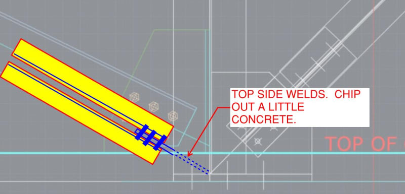
where due to geometry a working point of 4inches above top of BP
(1 inch above slab)
seems barely plausible

if eccentricity could be considered as 1" instead of 4" would be nice
 
In the first case, you're not going to be able to zero out your moment. Moment will be equal to the vertical component of your brace force times the distance from the bolt group centroid to the centerline of the column. You can only zero them out if you have an adequate connection between the gusset and the base plate. In other words, the moment's always there, it's just a matter of how you resist it. Your first sketch can only resist it by bending the column.

The second one, I'd say you're stuck with the 4".
 
Sorry for the delay. As you know, I've been a bit distracted today.

For the initial case, I feel as phamENG does: you're stuck with moment in the bottom of the column no matter what you do. And, by the sound if it, you're lateral resistance will be at about slab mid-depth regardless of the resisting mechanism you choose to claim. As such, I would locate the work point above the slab with the goals of:

1) making the connection as compact as possible and;

2) configuring things such that the gusset need not resist in plane bending.

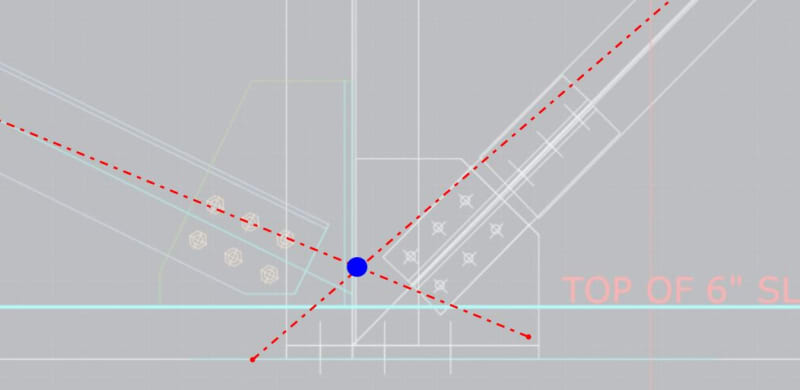
For the second case I would use a similar strategy but ensure that the work points for the two diagonals are coincident. That way, the column only sees the moment associated with the net difference in x-component force between the diagonals. With the work points for the two diagonals offset vertically, you may just be inviting a bunch of unnecessary moment into the column.

The second case is a bit confusing to me. Are the gusset and brace on the right hand side of the column existing?

c01_xwpg4b.jpg


c01_vktp6r.jpg
 
Also, what do you want the mechanism resisting lateral base plate shear to be? The bolts? Or the slab?
 
@KootK

ahaha no prob with the late response
appreciate it altogether

would you be opposed to this for the first

march8th_i8cv7j_ohixo9.jpg


and yes second brace in white is existing

are you suggesting to move the working point based on selected mechanism?
 

You are expected to calculate with eccentricity = new WP level - base plate level for the new bracing. If 4", yes the additional moment shall be calculated for ecc. 4". You shall check also the base plate , anchors for shear also. The existing and new bracing lateral forces could be additive..
 
yea for second case even if working point is the same

β will probably be diff
 
OP said:
would you be opposed to this for the first

I'm not opposed to it but, like I showed, my own choice would be to abandon the attempt at a truly concentric work point.

OP said:
are you suggesting to move the working point based on selected mechanism?

Yeah, it's a different story with the brace on the right being existing though. If the eccentricity is hurting you, I don't feel that it would be a huge deal to chip out a little concrete, do a detail like the one shown below, and grout things back in.

c01_khenzo.jpg
 
@kootk thanks for the help

i guess the analysis will reveal the optimal configuration
 
to clarify position of forces

phamENG suggested lever arm from centroid of bolt group to centerline of column

in dg29 UFM for CBB

the strong axis case the V*e[sub]c[/sub] along with H*e are considered to develop H[sub]column[/sub] and H[sub]baseplate[/sub]

this takes into consideration V acting at gusset column interface (at mid-height of gusset?)

said H[sub]c[/sub] is used in tension yielding of gusset on gross area at interface

in dg29 special case 3 however (gusset to beam only at joint)

H (presumably V rotated [ponder]) is only considered for shear yielding
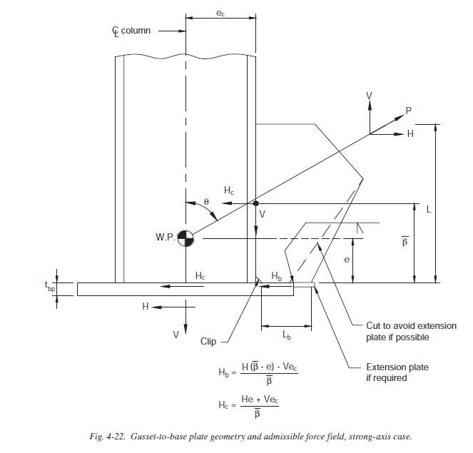
no H * e[sub]b[/sub] (presumably V * e[sub]c[/sub]) used

and tension yielding is built from V and V( - ∝)

you guys have any input on this?

thanks and much appreciated


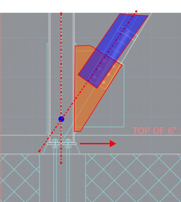
kootk i think im understanding what you are saying now you would raise your working point to coincide with the centroid of the gusset?

to get uniform forces on the gusset edges
 
Exactly. In theory, raising the work point also increases the moment coming into the column from the base shear reaction so that's your tradeoff with that.
 
If one drops the "node and line" view of things and considers the connection in it's true proportions:

a) Little bending will occur in the column where the column is buttressed by the gusset.

b) Unfortunately, in doing the buttressing, additional moments will be induced into the gusset.

I don't know what to say... connection design is just difficult and annoyingly imprecise for deep thinkers. Sometimes I have to just throw the blinders up and fire up some software to keep things moving forward.
 
Status
Not open for further replies.

Part and Inventory Search

Sponsor

Back
Top