Continue to Site

Eng-Tips is the largest engineering community on the Internet

Intelligent Work Forums for Engineering Professionals

  • Congratulations waross on being selected by the Eng-Tips community for having the most helpful posts in the forums last week. Way to Go!

Bolted connection for a beam in bending 12

Status
Not open for further replies.

HanStrulo

Civil/Environmental
Apr 16, 2021
117
Happy Monday everyone,

I have a new challenge and I am not sure how to approach it.
I have a beam in classic bending (max bending at the middle) and I want to install it using bolts.
The beam will come in two sections that i have to join in the middle( where the max moment is). I have never done a bolted connected design for anything other than tension and shear and I have no idea how to approach this challenge.

Any methodology? references? examples?

Thank you
 
Replies continue below

Recommended for you

Bolted Flange Plate Moment connection would be my choice. I'd also use slip critical bolts.
 
So you'll have a splice, three(?) separate plates (upper and lower caps and the web) ?
So the moment is a couple between the upper and lower caps, P/n (yes?)
design so that the bearing allowable is less than the shear allowable ("Slip critical", yes?)

another day in paradise, or is paradise one day closer ?
 
Use stiffened end plates at the splice with a shim if necessary to allow clearance and welded-bolted clip angles at the supports. I don't like to splice mid span and if possible can it be at 1/3 point?

Rather than think climate change and the corona virus as science, think of it as the wrath of God. Feel any better?

-Dik
 
So I need to write a moment as a couple force in the lower and upper flanges and then design the bolts for that shear?

Can i ask why it should be slip critical? is there something special about this type of connection?

@dik: i could design it at 1/3 point too but the idea is to get it as easy to install as possible and that would require a middle connection. is there any specific risks associated with that?

Thanks for the comments
 
Yes to resolving moment into force couple.

But bolts may be in tension or shear depending on which way you design the connection (e.g. end plate vs flange plates) EDIT - As pointed out below I have amended to be more clear.

For general applications I do not believe there is a requirement for slip-critical bolts in a beam moment connection. However, to some it is considered good practice to oversize the holes for erection tolerance purposes (see best good rules guide here specifically point 2) and if the holes are oversized you WILL need to specify pre-tensioned bolts.
 
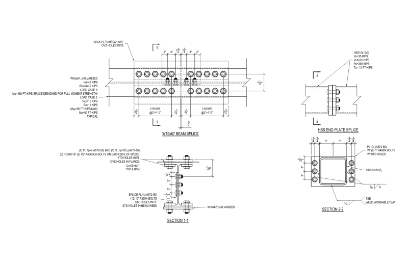
Just to provide beam-splice connection design concepts and to clarify some of the points made by others, here are a couple examples of splices I have done recently:

Splice_Examples_ckhvyj.png


Your bolt/weld selections are going to be determined by your force types and magnitudes. For your shear demand, there is a semi-decent example of a single plate splice in the AISC examples. There are also some examples for fully-restrained (FR) moment connections you can use for your flange bar/plate design. End plates are sometimes viable, and you can find design examples in the AISC examples and a few AISC Design Guides (4 and 16 I think).

However, based on the questions you're asking, and the chosen location of the splice, I think you should talk to your local grey-haired expert. No offense intended.

*Edited to add a .pdf file because the resolution on the .png isn't so good.
*.pdf upload didn't work. Bah!
 
@DrZoidberWoop Thank you for the drawing reference.

Unfortunately there is no grey haired expert and i can only consult with kind strangers online.

Since everyone agrees that a middle of the beam connection is a bad idea. I will suggest placing it at the 1/3 location. I will check the design example in the AISC for how to actually design it.

i forgot to say that the connection will not be permanent. we have a requirement for a beam to support some temporary work and the idea was to do bolted assemblies to save time. so i am not sure if the design should be as strict as a slip critical connection.

thanks
 
I'm a contractor and most of my designs are for temporary works. So please let me impress upon you that structural failures tend to happen while buildings are being erected, not after they are fully built. If you would require a slip critical connection in permanent application then please put it in for temporary works (especially if this is a one-off to save time/money anyways). Temporary works is not the place you want to skimp. Redundancy is reduced and stupidity is high during construction.

Good luck


What beam size? and what shear? and what moment and grade of steel, if I may ask...

Rather than think climate change and the corona virus as science, think of it as the wrath of God. Feel any better?

-Dik
 
"but bolts are in tension (not shear) from this" ... well, that depends how you make the splice.

You could make it a tension fitting, bolts aligned to axis of the beam, but I wouldn't. But I can see why you might do this (particularly if you weld an endplate on the presumably I beam).

I'd make it a shear splice. If I could I'd splice on the outside of the I (one plate top and bottom), if I had to I could splice on the inside with two straps.
and a simple web splice.

Lick o'paint.

another day in paradise, or is paradise one day closer ?
 
If you go with a bolted flange plate connection, check flexural rupture of the beam early in the design. There's a good chance it'll control and the only real way to approach that situation is to change the beam size. AISC Spec. Eq. F13-1.
 

@dik

The Beam is W24x104.

It's usually installed by welding the ends to the supports but the idea here is to prefabricate the the beam and the support and bolt it in the middle at site.

The moments it experiences are about 800KN.m in the mid span.

Steel grade is A35.

@ Enable

Words to live by.
 
Thanks rb1957. Quite obviously if the bolts are in tension or shear depends on the orientation of the splice connection and I should have mentioned that. Too quick off the draw. I must have had end plate in my mind because that was bantered about. But surely if flange plates are used the bolts would be in shear. And you are correct typical would be the flange connection (such as Dr.Z's detail).
 
and the Shear? and is the moment factored?

Rather than think climate change and the corona virus as science, think of it as the wrath of God. Feel any better?

-Dik
 
@dik
The moment is factored and the shear is 1300 KN approximately.
 
Dr. Z, do you get any questions from the field about a 1 3/4" space from the member face to the bolt CL? I was detailing a moment connection yesterday, and that would have helped in my case.

DrZ_Q_cgefwc.jpg


I hope you have someone to check your design.
 
For bridges, we'd call that a bolted field splice, a very commonly needed design. The AASHTO Bridge Design Specifications have a design methodology (Section 6.13.6 of the LRFD editions). The NSBA has design software that I believe is available for free.

On the subject of designing it as a slip-critical connection, for bridge girders, it is for geometric control, to prevent sag for the in-service condition. I would expect it would be the same for this situation. Would the kink in the beam that would result from it being assembled as a bearing-type connection be acceptable?

Rod Smith, P.E., The artist formerly known as HotRod10
 
Status
Not open for further replies.

Part and Inventory Search

Sponsor