Continue to Site

Eng-Tips is the largest engineering community on the Internet

Intelligent Work Forums for Engineering Professionals

  • Congratulations waross on being selected by the Eng-Tips community for having the most helpful posts in the forums last week. Way to Go!

Back to Back Channels as Column

Status
Not open for further replies.

PSSC

Mechanical
Feb 11, 2008
63
I work in industrial equipment. When visiting sites I like to look at the existing equipment. I have seen things I had not thought of and was very impressed by and seen things that made me uneasy to climb on said equipment.
I have seen in the past (when visiting job sites with older equipment) a situation where back to back channels have been used as field joints and simultaneously as columns to baseplates. It is rare but I have seen it, usually the field joints are between the columns and the columns are W beams.
The channels were bolted together through the web with no connection flange to flange on the outside, I do not know about the flanges on the inside of the equipment but I assume they were not connected either. The bolt pattern in the web was usually a staggered two row pattern. The two channels are both field welded to the base plates.
It is my intuition that these two channels are not acting as one composite member without the flanges connected. It is my intuition that the bolts through the web are not enough to make this a composite shape. I am having a hard time explaining why I see it this way (to the higher and fewer).
A counter argument is that the bolts closest to the outside flange are close enough to prevent independent buckling in the flange even if the flanges are not physically connected.

Does any one have an idea of a procedure that would help me figure out if the staggered bolt pattern in the web of two back to back channels is sufficient to create a composite shape.
My intuition is no, but that is not enough.

 
Replies continue below

Recommended for you

I would check:

- Total axial load considering the combined section as one member
- Load in each individual channel(half of the axial load if they're the same size), with the unbraced length equal to the distance between fasteners

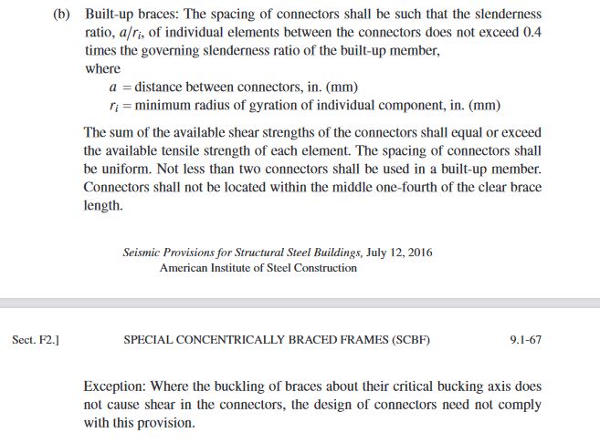
This isn't any different than say, a built up brace in a braced frame. AISC 341 has some requirements for this connection for seismic systems which you can check out to make you feel warm and fuzzy.
Capture_bm5gv4.jpg
 
Are you concerned about torsional buckling? For torsional buckling, I would evaluate both as separate columns. For lateral buckling, I would have no problem treating them as a composite shape, although the math I suppose could get tricky. You could simply check that the bolts are sufficient to resist shear flow between the members that would occur if it were to develop the weak axis moment capacity. Where it gets tricky is lateral torsional buckling, but based on your description I don't think this will be a controlling limit state. For local flange buckling, whether or not the shapes are composite has no effect.
 
Check longitudinal shear against the frictional force from the bolts.
 
OP said:
Does any one have an idea of a procedure that would help me figure out if the staggered bolt pattern in the web of two back to back channels is sufficient to create a composite shape.

As mentioned previously, design standards usually have some canned guidance for this and that's what I'd go with in regard to the fastening pattern. It's a bit of a weird problem in that there's really no fastener shear to design for until after something starts to buckle. I've got some papers on this kicking around somewhere but a) differential equations and b) I don't believe that folks are getting anywhere near this fancy in routine design.

canwesteng said:
Are you concerned about torsional buckling?

That's where my mind went to first as well and, frankly, thinking about it makes my head hurt. That said, I feel that this may not actually be that serious of a concern. Consider:

1) Most of the system's torsional resistance should originate from warping torsion, as with wide flanges. And whatever composite connection gets the job done for weak axis buckling would likely do the same job for any buckling mode involving warping torsion.

2) While it's likely of little significance, I feel that even the St.Venant torsion would behave mostly compositely. So long as the connections forced the two pieces to experience rotation about a common point in space, the torsion stress loops in the flanges should be functionally identical to what you'd see in a wide flange. The only sacrifice would be the modification to the torsion stress loop in the webs: their tendency to act as something between a single web with a single torsion loop and two webs with two, independent torsion loops.

3) In a lot of vintage applications, you'll see this setup with the channels spaced and connected with batten bars. Essentially a tubular member then with killer torsional properties.

canwesteng said:
You could simply check that the bolts are sufficient to resist shear flow between the members that would occur if it were to develop the weak axis moment capacity.

An approach that I've seen for axial is to assume that 2%-5% of the axial force in the member exists as a lateral point load at mid-height. Then design for the shear associated with that. For torsional concerns, maybe use those same loads but applied to both flanges, similar to the bi-moment concept for torsion. This might be less onerous than designing for the weak axis capacity.

OP said:
A counter argument is that the bolts closest to the outside flange are close enough to prevent independent buckling in the flange even if the flanges are not physically connected.

I would say that's pretty accurate from the perspective of both global lateral buckling and warping torsional buckling.
 
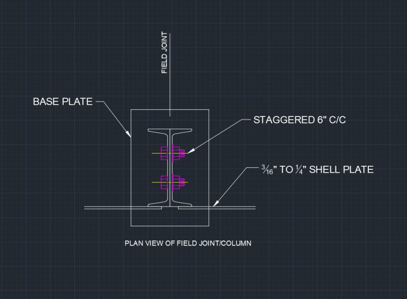
BACK_TO_BACK_xjqsm5.jpg


This is a plan view cut through the column/field joint as I saw it in the field. I want to say the shell plate would not allow rotation. I see the shell as a brace to weak axis Lateral Buckling. While strong axis could use a portion of the shell I probably wouldn't.
 
For a typical version of this where the channels are really just stiffening elements for transvers load on a shell plate:

1) The channels would be primarily used in strong axis flexure.

2) You would technically get composite strong action flexural resistance (no better than 2x non-composite) without any fastening so the bolts really only serve to improve load sharing and, perhaps, torsional buckling resistance.
 
Status
Not open for further replies.

Part and Inventory Search

Sponsor